Author: Jonas M. A. Chenderasa
Supervisor: Arjan Habraken (TU/e), Emanuela Bosco (TU/e), Roy Crielaard (Arup)
Thesis defended 7 May 2026
Bamboo is a fast-growing grass that has been used as a building material for centuries. Moso bamboo (Phyllostachys edulis) can be harvested for structural use after only 4 to 5 years, an order of magnitude faster than softwood, and potentially stores CO2 on each growth cycle while delivering an along-grain characteristic strength significantly exceeding softwood.
But despite its natural beauty, full-culm bamboo carries practical drawbacks for structural work: the round hollow cross-section does not work easily with rectangular architecture, the low weight-to-volume ratio makes shipping in culm form inefficient, and untreated bamboo is less durable than timber. Engineered bamboo removes most of these limitations. Laminated bamboo lumber (LBL) is the direct analogue of glulam, with bamboo lamellae glued into dimensioned beams and columns.
The barrier to using LBL for a structural purpose on a larger scale in Europe is rather regulatory than mechanical. Eurocode 5 (EC5), the design code for timber structures, does not cover LBL, so every project that wants to use it has to apply for a special project approval, which significantly impacts project cost and duration. Aligning LBL with EC5 would remove that per-project hurdle and let LBL contribute its carbon-storage potential.
Building with LBL means designing connections between members. The most common timber connection uses dowel-type fasteners, which need to be checked for loading perpendicular to the grain. That is the direction where LBL, like timber, is weakest, so the design check for these connections has to account for fracture.
A dowel connection loaded perpendicular to the grain can fail in two ways: brittle splitting, where a crack runs along the grain, or ductile embedment, where the fibres crush under the dowel. EC5 takes the connection capacity as the smaller of the two. The splitting branch is the specific gap this thesis closes. It tested whether the splitting equations in EC5 Gen 1 (Eq. 8.4) and EC5 Gen 2 (Eq. 11.54) apply to LBL dowel connections and, where they do, calibrated their parameters against LBL data, so the code can be applied. The two equations are:
Gen 1 packs everything into a single splitting constant Ck (= 14 for softwood timber). Gen 2 splits that role between a material factor kmat and a density correlation kG, and applies the load-duration kmod and partial-factor γM inside the resistance side. The thesis recalibrates Ck for Gen 1 and kmat for Gen 2.
Main research question
How can the splitting capacity of Laminated Bamboo Lumber with dowel-type connections loaded perpendicular to the grain be established under the Eurocode 5 framework?
What was done
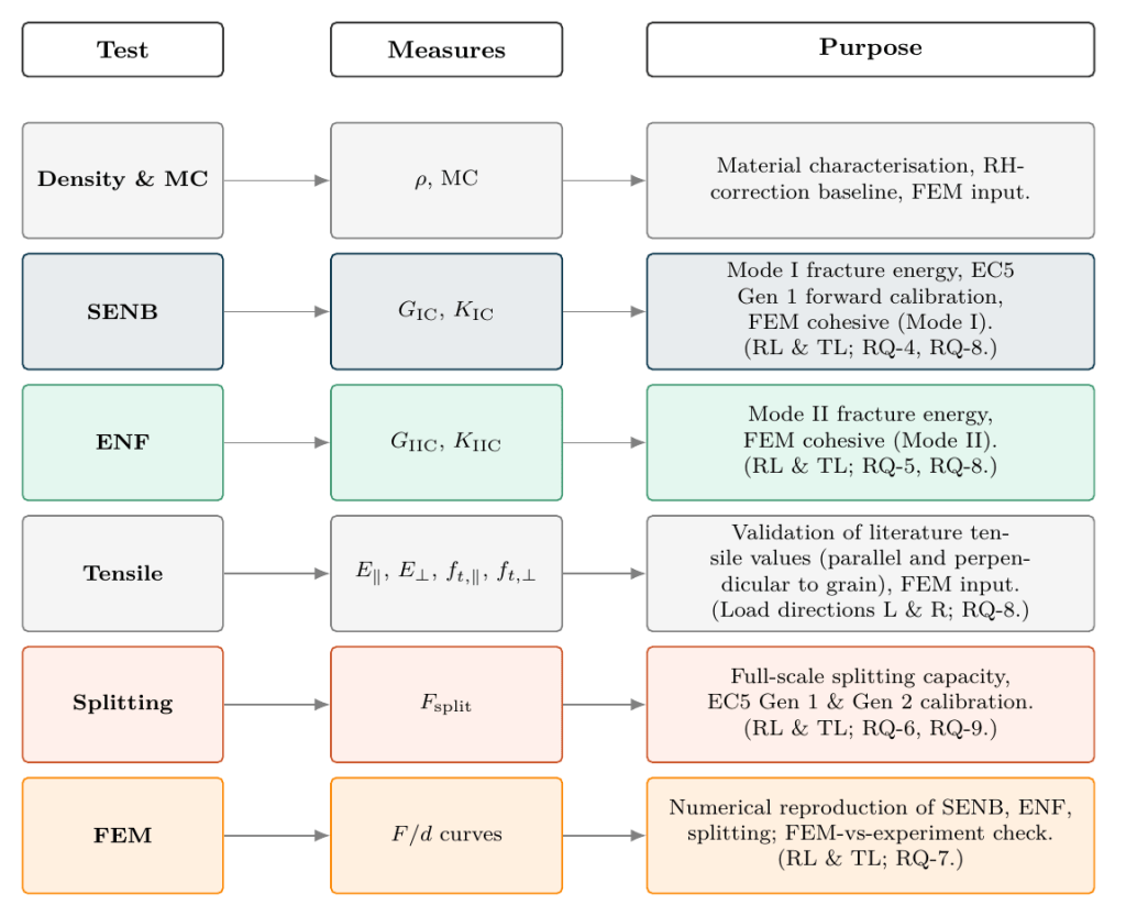
The work combined small-scale fracture tests, full-scale splitting beams, and cohesive-zone finite-element simulation. The test matrix gives the full picture in one image, mapping each test and each FEM run to the property it measures.
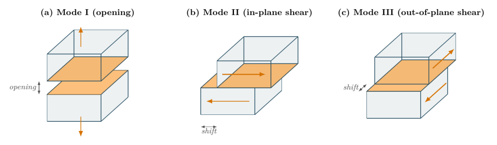
Splitting is a fracture-mechanics problem, and two terms from that field anchor the rest of the page: the fracture mode (how a crack opens) and the crack system (how the crack is oriented in an anisotropic material like LBL).
A crack can grow by opening (Mode I), in-plane shear (Mode II), or out-of-plane tearing (Mode III). Splitting in a dowel connection is Mode I dominant. The small-scale tests isolated Mode I with the single-edge notched bending test (SENB) and Mode II with the end-notched flexure test (ENF), both run on two specimen thicknesses, with NT BUILD 422 as the primary calculation method for Mode I and CBBM for Mode II.
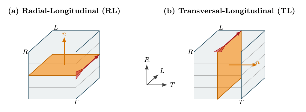
LBL is anisotropic about three principal axes: longitudinal L (along the fibres), radial R, and tangential T. The lamellae can be glued into a structural section in two orientations. A flatwise section stacks the lamellae with their seams running parallel to the top edge, while an edgewise section stands the lamellae on their long edge so the seams run perpendicular to the top edge.
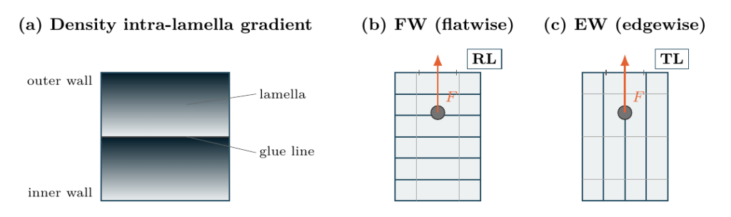
The crack system labels how a crack is oriented in an anisotropic material with two letters: the normal to the crack plane, then the direction of propagation. For perpendicular-to-grain loading, a flatwise section gives the RL (radial-longitudinal) crack system, and an edgewise section gives the TL (tangential-longitudinal) crack system. The thesis tested both systems.
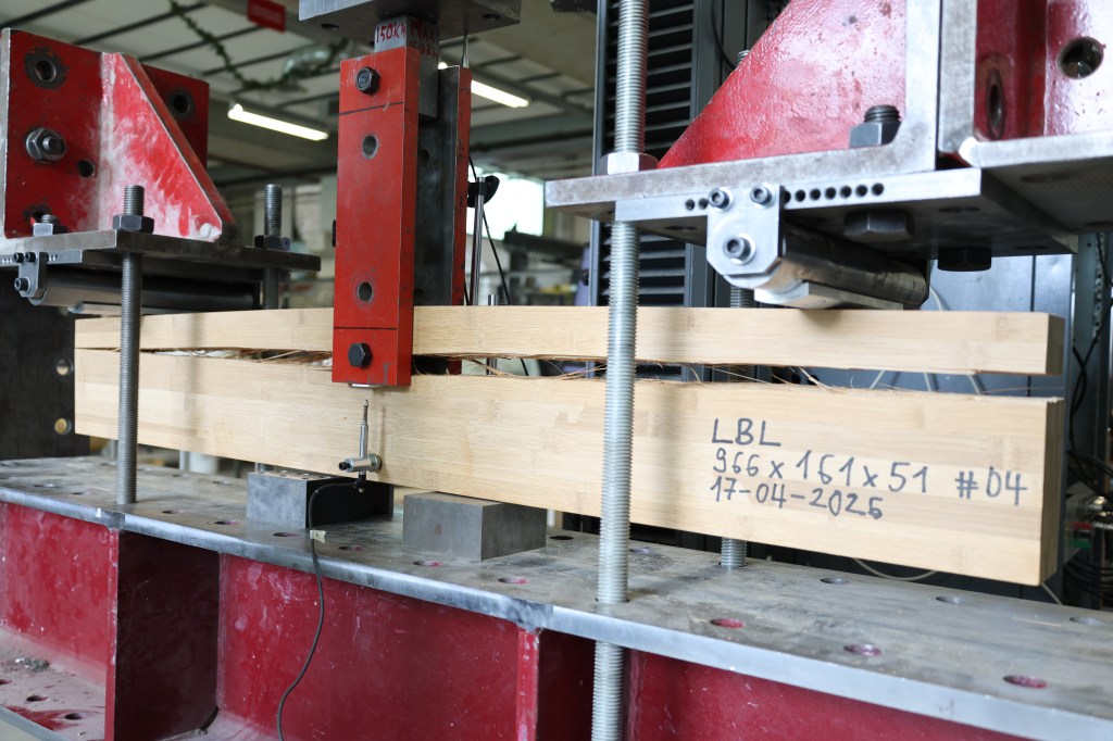
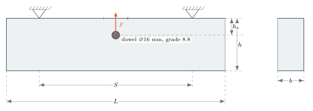
The full-scale splitting tests took four specimens per geometry: flatwise (RL) at 1200 × 200 × 40 mm and edgewise (TL) at 960 × 161 × 51 mm, with a single 16 mm grade 8.8 dowel at α = he/h = 0.32.
The simulation work mirrored each experiment in LS-DYNA with cohesive elements placed along the experimentally observed crack plane, with the material GIC values fed in directly from the SENB measurements.
Small-scale fracture results
The Mode I energy release rate GIC came out of 62 SENB specimens across both crack systems and two specimen thicknesses, calculated using NT BUILD 422. The overall mean was about 200 J/m², split as 210 J/m² in RL and 190 J/m² in TL.
The Mode II energy release rate GIIC came out of 50 ENF specimens, calculated primarily using CBBM, averaging about 9100 J/m² in RL and 8200 J/m² in TL. The same RL-above-TL ordering held as in SENB, but the ENF curves carried more scatter because the specimens fail in mixed mode rather than in clean Mode II. Other calculation methods (SBT, TBT, CCM) returned values from roughly 1100 to 9700 J/m², reflecting how sensitive a Mode II calculation is to the assumed Mode I / Mode II partition.
Full-scale splitting results
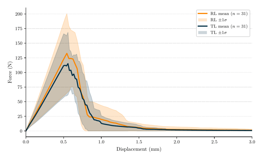
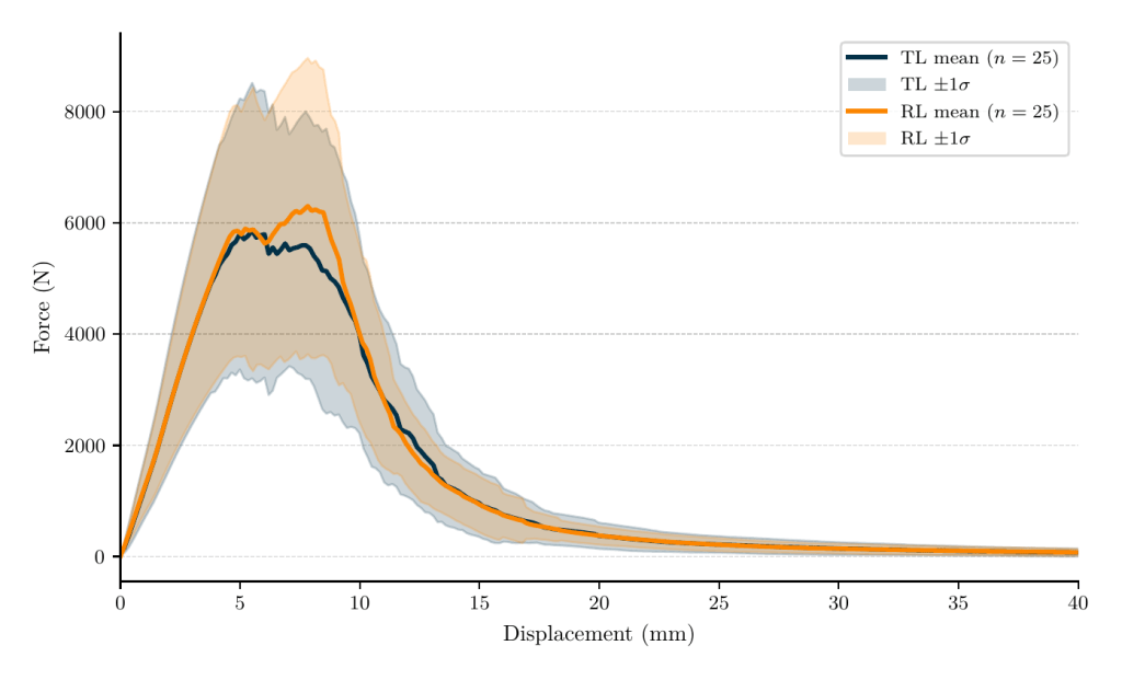
In each splitting beam the dowel was loaded until the beam split. The force rose linearly with mid-span deflection up to a peak and then dropped as the crack ran. The shape of the force-deflection curve was consistent across all eight specimens, with edgewise (TL) beams reaching lower peak load than flatwise (RL) beams.
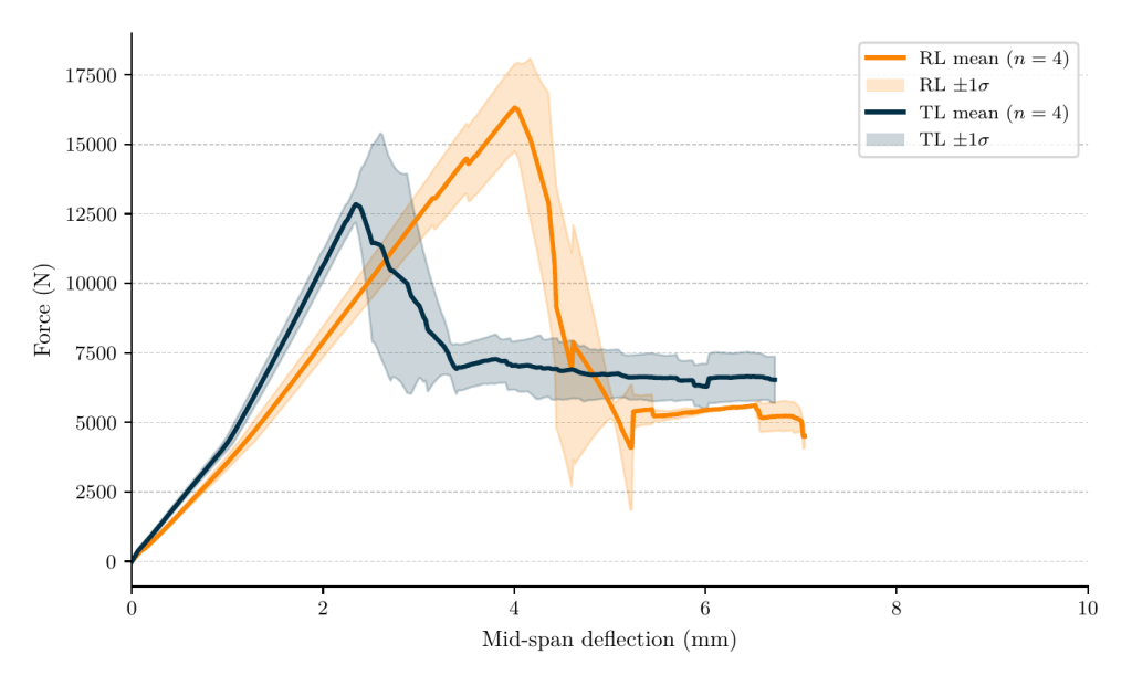
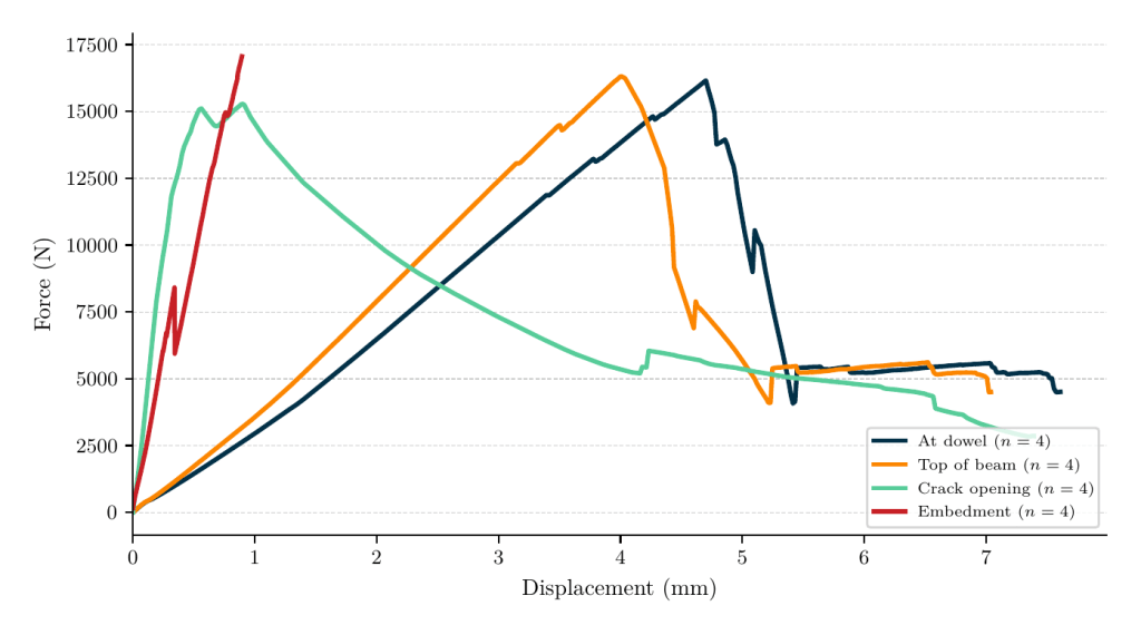
A decomposition of the dowel and top-of-beam displacement, together with a derived embedment displacement, separates the local crushing of the bamboo at the dowel hole (the red trace) from the rest of the response. Embedment displacement stayed small compared with the other channels, peaking under 1 mm before the beam split.
Across all eight beams, the cracks ran along intra-lamella fibre interfaces, and no glue-line separation was observed, with the splitting Mode I dominant in every test.
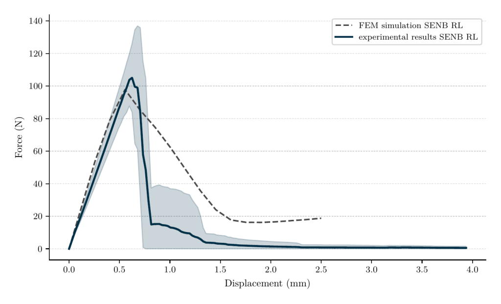
FEM simulation
The LS-DYNA prescribed-crack-path (not predictive) models, attempted to reproduce the experimental tests. The match was strong for SENB and for the full-scale splitting beams, weaker for ENF. The ENF gap traces to the prescribed planar crack path being too simple for the stepped, mixed-mode fracture surface that ENF develops on LBL.
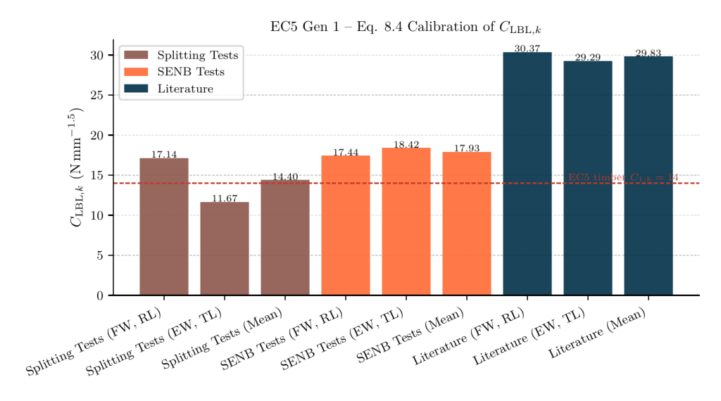
EC5 Gen 1 calibration (Eq. 8.4)
Gen 1 writes the splitting capacity as a single material constant C. Calibration is the question of what value of that constant best fits the data. The thesis ran two independent calculations: a calculation of the constant from the full-scale splitting peak loads, and a calculation from the SENB-derived fracture energy combined with a literature-derived shear modulus.
The calculation from the full-scale tests returned CLBL,k ≈ 14.4 N/mm1.5, within 3 % of softwood’s calibrated Ck = 14. The calculation from SENB returned CLBL,k ≈ 17.93 N/mm1.5. Both results sit in the 14 to 19 N/mm1.5 range that is comparable to softwood timber, so Eq. 8.4 applies to LBL without modification. Splitting into the two section build-ups gives flatwise C ≈ 17.14 against edgewise C ≈ 11.67, with flatwise about 46 % higher than edgewise. Designers using an edgewise build-up should use 11.6, not 14.4.
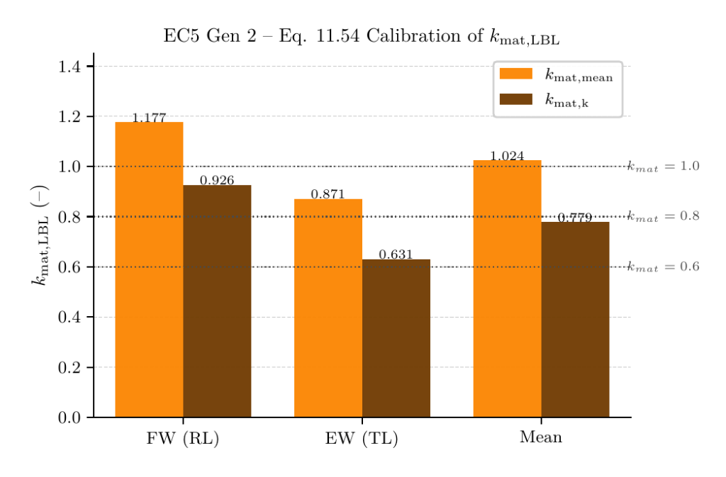
EC5 Gen 2 calibration (Eq. 11.54)
Gen 2 replaces the single constant of Gen 1 with a material factor kmat multiplied by a density correlation kG. The thesis only recalibrates kmat for LBL and leaves kG untouched. For the calibration, an LBL density of 700 kg/m3 is assumed.
Pooling the mean of both crack systems gives a calibrated kmat,LBL = 0.779, which the thesis rounds down conservatively to kmat,LBL = 0.7. The proposal is to add LBL as a new entry to the Gen 2 material-factor lookup, giving:
Per-section: flatwise kmat ≈ 0.93, edgewise kmat ≈ 0.63, the same flatwise-above-edgewise pattern as Gen 1. Designers using an edgewise build-up should use 0.6, not 0.7.
Limitations and future research
The numbers above are a first-run calibration, not a final design value. They assume designers use the recommended flatwise section build-up (RL), not the edgewise build-up (TL). They rest on only 4 specimens per geometry, a single edge-distance ratio (α = 0.32), a single 16 mm dowel, and dry indoor conditioning (35% RH) at an average 4.55 % moisture content. The work covers LBL from Moso bamboo (Phyllostachys edulis) and dowel-type connections only. Embedment strength and overall load-carrying capacity are out of scope.
Natural next steps include characterising embedment strength and partial-factor γM for LBL, extending the splitting calibration to multi-dowel groups and other edge-distance ratios, quantifying the moisture-content effect, and feeding the calibrated splitting capacity into a full EC5 connection-design check that includes load-carrying capacity.
Conclustion
The splitting capacity of LBL dowel connections loaded perpendicular to the grain fits the Eurocode 5 framework. EC5 Gen 1 (Eq. 8.4) transfers to LBL with CLBL,k ≈ 14.4 N/mm1.5, within 3 % of softwood’s Ck = 14, and no separate material factor is required. EC5 Gen 2 (Eq. 11.54) needs a new entry in the kmat lookup, calibrated here to kmat,LBL = 0.7, between sawn timber (0.6) and panels and LVL-C (0.8). Section build-up matters for both generations: flatwise (RL) is the recommended default, with a designer using edgewise (TL) needing to drop to the per-system values from the calibration. Splitting in all eight full-scale tests was Mode I dominated, with intra-lamella fibre delamination and no glue-line separation observed in any test.
Selected References
For full citations see the full-test thesis.
Harries, K. A., & Trujillo, D. (2025). Opportunities and limitations for the design of engineered bamboo structures using design standards for wood. Journal of Building Engineering, 114, 114125. https://doi.org/10.1016/j.jobe.2025.114125
Al-Rukaibawi, L. S., Kachichian, M., & Károlyi, G. (2024). Mechanical properties of laminated bamboo lumber N-finity according to ISO 23478-2022. Journal of Wood Science, 70(1). https://doi.org/10.1186/s10086-023-02115-z
Jonasson, J. et al. (2024). Fracture energy of birch in tension perpendicular to grain: experimental evaluation and comparative numerical simulations. Wood Science and Technology (2024) 58:1925–1949 https://doi.org/10.1007/s00226-024-01595-6
Gómez-Royuela, J. L., Majano-Majano, A., Lara-Bocanegra, A. J., Xavier, J., & de Moura, M. F. S. F. (2024). Experimental and Numerical Research on the Splitting Capacity of European Beech Beams Loaded Perpendicular to the Grain by Connections: Influence of Different Geometrical Parameters. Applied Sciences, 14(2), 900. https://doi.org/10.3390/app14020900
Chen, Y. et al. (2023). A Review of Experimental Research on the Mode I Fracture Behavior of Bamboo. Journal of Renewable Materials 2023, 11(6), 2787-2808. https://doi.org/10.32604/jrm.2023.027634
Reynolds, T. P. S., Sharma, B., Serrano, E., Gustafsson, P.-J., & Ramage, M. H. (2019). Fracture of laminated bamboo and the influence of preservative treatments. Composites Part B: Engineering, 174, 107017. https://doi.org/10.1016/j.compositesb.2019.107017
Sharma, B., Bauer, H., Schickhofer, G., & Ramage, M. H. (2017). Mechanical characterisation of structural laminated bamboo. Proceedings of the Institution of Civil Engineers – Structures and Buildings, 170(4), 250–264. https://doi.org/10.1680/jstbu.16.00061
Schoenmakers, JCM (Dennis). (2010). Fracture and failure mechanisms in timber loaded perpendicular to the grain by mechanical connections. Technische Universiteit Eindhoven. https://doi.org/10.6100/IR673053
van der Put, TACM., & Leijten, AJM. (2000). Evaluation of perpendicular to grain failure of beams caused by concentrated loads of joints, V31 september 2000. Delft University of Technology. https://research.tudelft.nl/en/publications/evaluation-of-perpendicular-to-grain-failure-of-beams-caused-by-c-2/
