Parametric FEM of HSB shear walls: Quantifying the effects of design parameters on racking response
Article by : David J. van Rossum
Supervisors: Ir. A.P.H.W. Habraken, Ir. Vincent Staat, Daan de Jager
Timber shear walls (houtskeletbouw, HSB) are key lateral‑load‑bearing components in low‑carbon timber buildings. They resist wind and seismic loads through a delicate load path involving studs, sheathing panels, mechanical fasteners and anchorage. Designers typically use simplified Eurocode‑based formulas, which are necessary for verification but offer little insight into how changes in fastener spacing, opening size or anchorage affect stiffness and internal forces. This thesis therefore develops a three‑dimensional parametric finite‑element model (FEM) to quantify how design parameters influence the racking response of HSB shear walls.
Parametric modelling approach
A Grasshopper–AxisVM workflow was created to generate and analyze shear‑wall variants automatically. Controlled input parameters define wall geometry, stud layout, sheathing configuration, fastener positions, support stiffness and loading. Grasshopper scripts produce the geometry and connector layout; the data is exported to AxisVM for nonlinear analysis; results are re‑imported for post‑processing. This automation allows hundreds of wall variants to be explored efficiently.
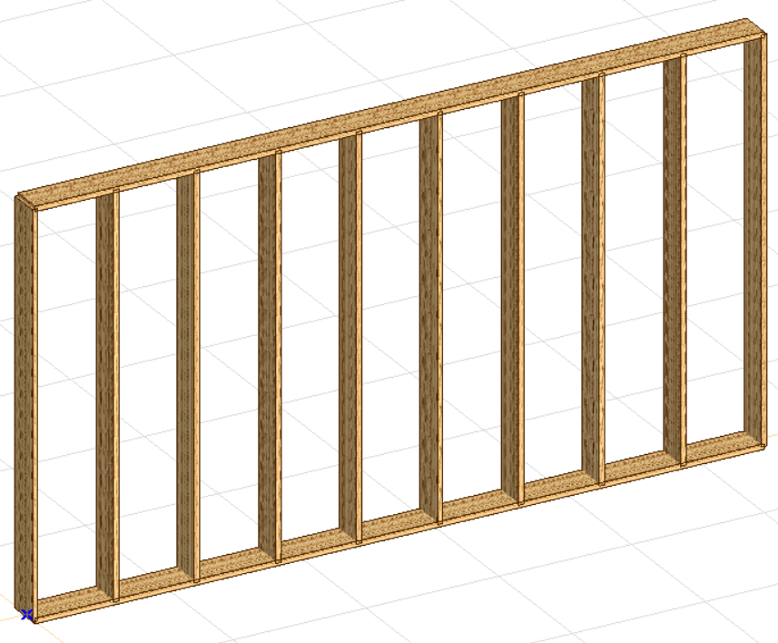
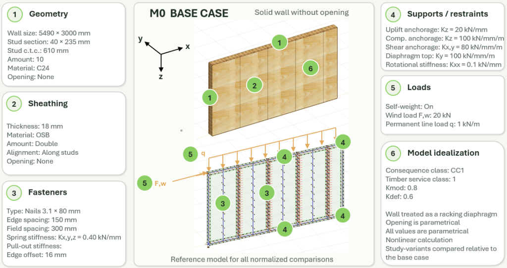
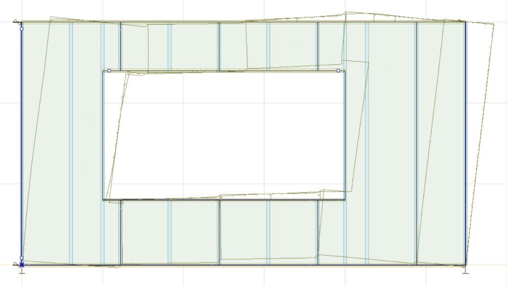
The base case (M0) – the reference for all comparisons – is a 5.49 m‑long by 3 m‑high wall with no openings. It has ten C24 studs (40 × 235 mm cross‑section) at 610 mm c-t-c and double 18 mm OSB sheathing. Nails (3.1 × 80 mm) are spaced 150 mm at the edges and 300 mm in the field, with an edge offset of 16 mm. Each nail is modelled as a 3D spring with a base stiffness of 0.40 kN/mm. The support system comprises uplift, compression, shear and rotational springs; uplift anchorage is 20 kN/mm and shear anchorage 80 kN/mm/m. The base loading includes self‑weight, a 20 kN horizontal wind load and a 1 kN/m vertical line load. Non‑linear analysis captures the interaction between stud bending, sheathing in‑plane stresses and fastener slip.
Base-case (M0) response
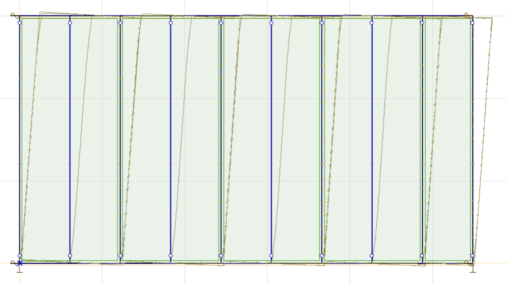
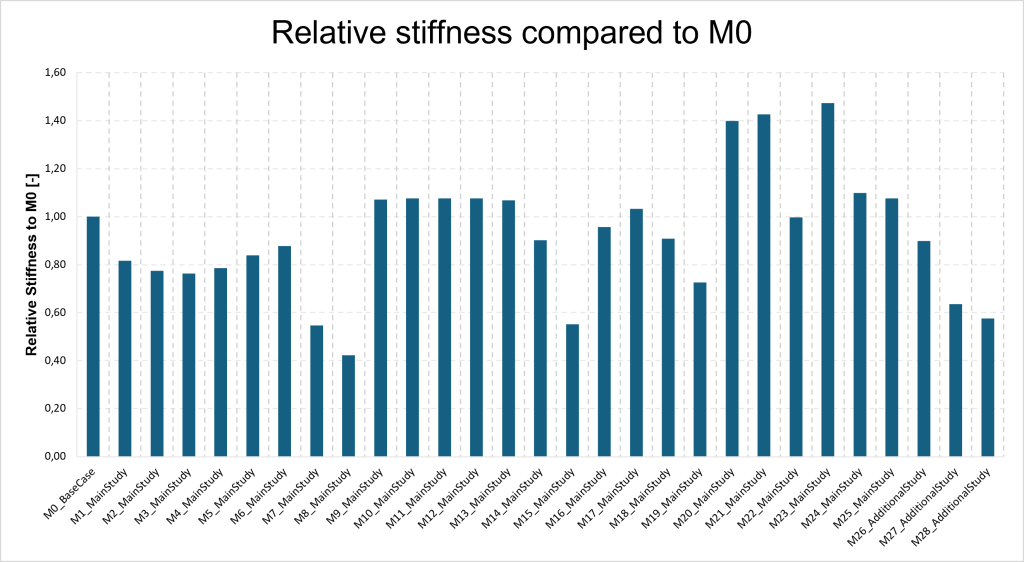
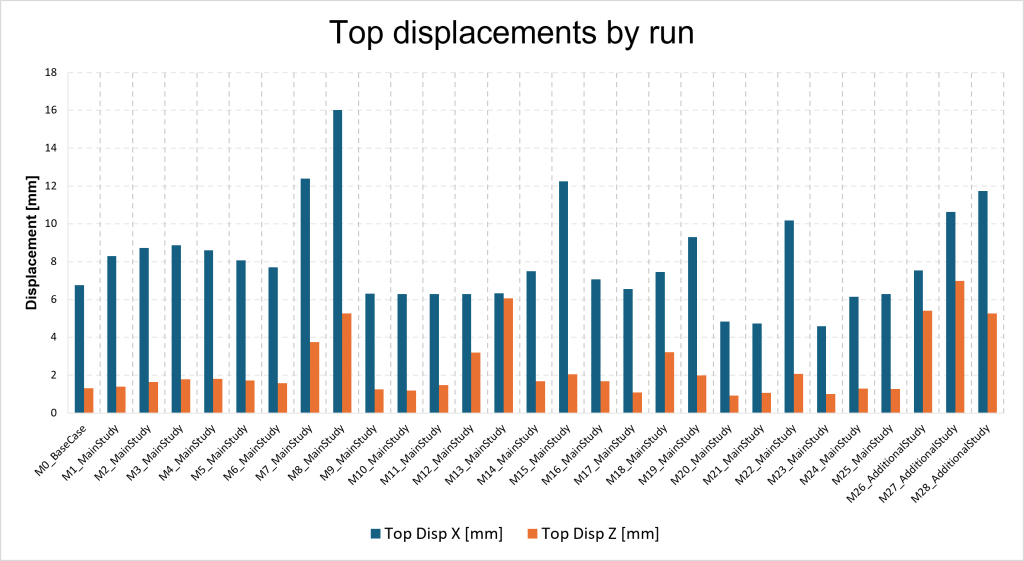
For the base case (M0), the analysis gives a horizontal top displacement of 6.765 mm under a 20 kN load, corresponding to a global racking stiffness of 2.956 kN/mm. This value serves as the reference for normalized comparisons. Each variant’s relative stiffness is defined as krel = ki/k0, where k0 is the base‑case stiffness.
Parametric study and variants
A total of 29 cases were analyzed: the base wall plus 28 variants. The study systematically varies opening position, opening size, anchorage density, vertical load, stud depth, sheathing amount, support stiffness, stud count, nail spacing, horizontal load magnitude, fastener stiffness, stud spacing, nail edge offset and the presence of a beam beneath the wall. Cases M1–M5 shift the door opening along the wall; M6–M8 widen a window opening; M9–M10 add extra hold‑down anchors; M11–M13 increase vertical load; M14 reduces stud depth; M15 removes one sheathing layer; M16–M18 alter anchorage stiffness; M19–M20 adjust the number of studs; M21 reduces nail spacing; M22 increases wind load; M23 increases nail stiffness; M24 halves stud spacing; M25 reduces nail edge offset; and M26–M28 place the wall on a loaded beam.
Key findings
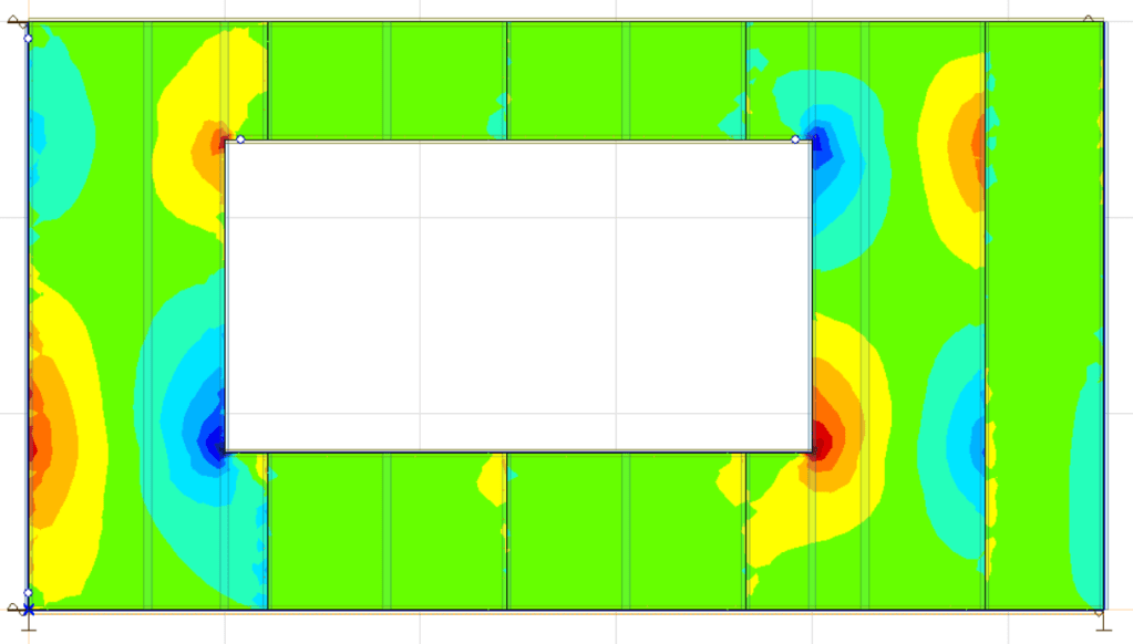
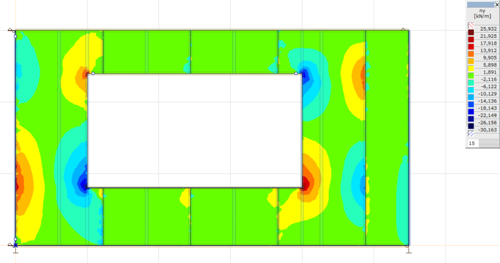
The most dramatic stiffness loss occurs for the largest window (3.0 m wide), case M8: the relative stiffness drops to 0.422 (i.e. about 42 % of the base stiffness). A single‑sided sheathing (M15) reduces stiffness to 0.552. These reductions are accompanied by large increases in nail forces and uplift demands – up to 30 kN uplift for M8. Opening eccentricity also matters: shifting the door alters stiffness even with constant opening area. The results show that the remaining wall segments contribute according to their position and ability to develop an efficient load path.
Connection properties are the most influential parameters. Reducing nail spacing from 150 mm to 100 mm (M21) increases relative stiffness to 1.426; increasing nail spring stiffness from 400 to 750 kN/m (M23) raises it further to 1.473. Adding more studs (M20) also improves stiffness (rel = 1.399), but not as dramatically. The dominance of connection behaviour confirms that sheathing‑to‑frame load transfer governs the wall response. However, a denser or stiffer connection system attracts higher local forces, so improved stiffness does not automatically mean a safer design.
Reducing the stud count from ten to seven (M19) lowers stiffness to 0.726, while halving stud depth to 90 mm (M14) yields a moderate drop (rel = 0.902). The single‑sheathing case (M15) again shows that sheathing continuity is critical: removing one sheathing layer causes a larger stiffness loss than reducing stud depth. Doubling stud density by halving spacing (M24) yields only a modest increase to rel = 1.099.
Adding extra hold‑downs (M9–M10) or changing uplift stiffness (M16–M17) increases stiffness slightly (rel ≈ 1.07). This suggests that the base wall is not primarily governed by insufficient uplift anchorage. Increasing the vertical line load reduces uplift demand and may suppress uplift completely, but it shifts demand into compression reactions, stud shear/moment and nail forces. Designers should thus consider uplift and compression together rather than assuming vertical load always benefits the wall.
The study also evaluated local nail forces, uplift/compression reactions, stud forces and sheathing stress. Large openings (M8), single sheathing (M15) and beam‑under‑wall scenarios (M27–M28) yielded high demand concentrations. While the studs remained below Eurocode unity checks in all cases, the nails exceeded unity in several variants. This underscores that the fastener system is both the main stiffness contributor and the most critical component.
Discussion & conclusion
The parametric FEM study confirms that design decisions about openings, sheathing continuity and connection detailing have first‑order effects on the racking response of timber shear walls. Simple reduction factors that ignore load‑path geometry or fastener behaviour cannot capture these effects. The model shows that:
Large openings and single‑sheathing arrangements dramatically reduce stiffness and increase local forces. Designers should minimise opening width or provide additional reinforcement (e.g., closer nail spacing or header beams) around openings.
Improving connections through closer nail spacing or stiffer fasteners yields the greatest stiffness gains, but these changes also intensify local demand. Designers should balance global stiffness benefits with local strength and ductility requirements.
Increasing stud count improves stiffness but less than enhancing connections. Conversely, reducing stud count or depth decreases stiffness markedly, emphasising the structural role of framing density.
Additional hold‑downs and vertical loading influence local uplift/compression balance more than global stiffness. Anchorage design should thus consider both uplift and compression paths.
This thesis demonstrates the value of a parametric FE workflow as a design‑support tool: it complements Eurocode checks by revealing how parameters interact and by highlighting where local demand concentrations occur. The same workflow can be extended with calibrated material properties and cyclic loading to develop design charts or simple factors for practicing engineers. Ultimately, understanding the relative influence of design parameters promotes more efficient and resilient timber buildings while advancing sustainable construction.
References
[1] All citations refer to sections of the thesis Parametric FEM of HSB shear walls: Quantifying the effects of design parameters on racking response.
