Optimised Dowel Configurations in DLT
Article by: Bonno van der Horst
Supervisors: Arjan Habraken, Rudi Roijakkers & Vincent Staat
Abstract
The construction industry is increasingly focusing on sustainability, with bio-based materials playing an important role in this transition. Mass timber systems such as Cross-Laminated Timber (CLT) and Glulam are widely used due to their lower environmental impact compared to conventional construction materials. However, many conventional Engineered Wood Products (EWPs) rely on synthetic adhesives or steel fasteners, which reduce recyclability and limit circularity.
Dowel-Laminated Timber (DLT) offers a fully biobased alternative. In DLT systems, timber lamellae are connected using hardwood dowels that act as shear connectors. The connection is created through the natural swelling behaviour of wood, eliminating the need for adhesives or steel components. Despite these advantages, limited research has been
conducted on optimising DLT systems for both structural and environmental performance.
This research investigated the effect of optimising dowel distribution along a beam with a fixed span length. The main goal was to achieve a target bending stiffness while reducing the amount of dowel material used. A multi-scale research approach was applied, including pull-out testing, slip modulus determination, analytical modelling, full-scale six-point bending tests, and a Life Cycle Assessment (LCA).
The results show that DLT beams behave as mechanically connected composite structures, where the bending stiffness strongly depends on the stiffness of the dowel connections. Full-scale testing demonstrated that the effective composite action was lower than predicted by connection-level tests. However, the bending moment resistance remained relatively unaffected, with experimental beams achieving capacities close to full composite action.
Optimising the dowel configuration resulted in a 45% reduction in dowel volume while reducing maximum bending stiffness by only 17.5%. Although this optimisation led to only a modest 2.6% reduction in cradle-to-grave CO₂-equivalent emissions, the LCA showed that DLT systems still achieved a significantly lower global warming potential compared to Glulam, NLT, and steel beam systems.
Introduction
Mass timber products are increasingly used in construction because of their lower embodied energy compared to conventional building materials. Common systems such as Cross-Laminated Timber (CLT), glulam, LVL, and Nailed-Laminated Timber (NLT) rely on adhesives or steel fasteners to connect timber layers. However, these materials raise concerns regarding recyclability, circularity, and human health (Hussin et al., 2022)(Bergsagel et al., 2025).
Recent studies show that fully reusing conventional mass timber products remains difficult, mainly because the residual strength of recycled timber is hard to determine (Liu et al., 2025). As a result, many products are downcycled, incinerated, or sent to landfill. In addition, glued timber products cannot easily be separated into reusable components, while steel fasteners in NLT complicate disassembly and can damage woodworking machinery during reuse (Bergsagel et al., 2025).
Synthetic adhesives, commonly used in engineered wood products, are also under increasing scrutiny. Although they provide strong and durable connections, they are fossil-based and may negatively affect indoor air quality (Hussin et al., 2022).
These challenges have led to growing interest in adhesive-free and nail-free alternatives such as Dowel-Laminated Timber (DLT). DLT consists of timber lamellas connected using wooden dowels, creating a fully biobased and recyclable structural system.
Current research on DLT mainly focuses on general mechanical behaviour using constant dowel spacing and diameters (Sotayo et al.,2020) (De Moraes Pereira et al., 2021). However, little attention has been given to optimising dowel configurations based on local loading conditions. Increasing dowel density near supports, where shear forces are highest, could improve structural performance while reducing material use in less critical areas (Yeh et al., 2024) (Lu et al., 2018). Furthermore, the environmental performance of optimised DLT systems throughout their full life cycle remains largely unexplored.
In this research, DLT beams are investigated through a multi-scale analysis. The study is divided into several levels of investigation, starting with the analysis of the contact behaviour between dowel swelling and the pre-drilled hole through pull-out resistance testing (micro scale). Subsequently, the connector stiffness is examined by means of double-shear testing to determine the slip modulus of the wooden dowels (meso scale). Using these results, the structural behaviour of the beam is analytically determined, after which the dowel configuration is optimised along the beam length. The optimised beam is then experimentally validated through a full-scale six-point bending test (macro scale). Finally, based on the structural performance obtained from the multi-scale analysis, DLT beams are compared with more conventional beam systems through a Life Cycle Assessment.
Pull-out Resistance
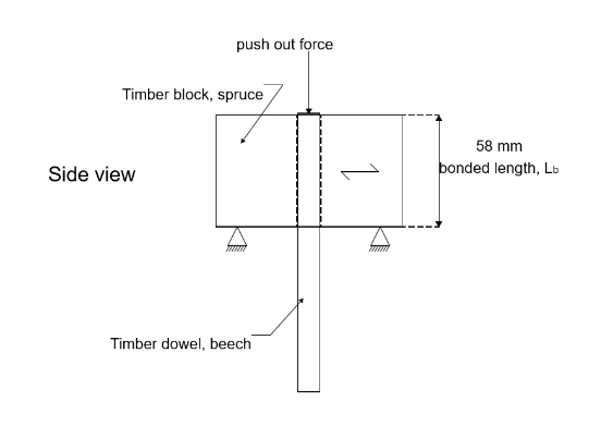
First, testing was conducted at the micro scale. In this phase, the clamping force resulting from the tight-fit connection was investigated, which is determined by the following equation:
Fpull = μpAc = μp(πDL)
In this equation, μ represents the coefficient of friction between the dowel and the bore wall (wood–wood contact), p denotes the contact stress between the dowel and the bore wall, D is the nominal diameter of the bore, and L is the bond length, which was 58 mm for all specimens.
In addition to the clamping force, the optimal oversize was investigated to achieve a manufacturable and mechanically robust connection. The selected oversize is based on the theoretical assumption that the beechwood dowels tend to swell, causing them to press against the bore wall of the spruce wood. For this research, a design interference level of 1% and 3% has been chosen to investigate.
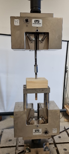
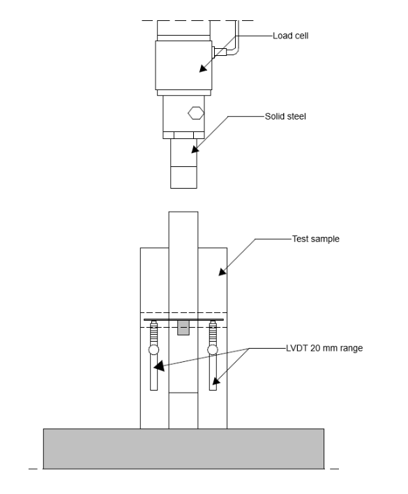
The experimental test setup was made with a beech wood dowel, with hole diameters 10, 16 and 20 mm, inserted into a pre-drilled hole in the spruce timber block. For all specimens, the embedment length was kept constant at 58mm, corresponding to the thickness of the timber block. The timber blocks had dimensions of 155mm x 155mm. The test setup can be seen in the figure below.
Due to manufacturing tolerances in the drilled holes and the fact that the dowels were produced based on the intended (design) interference levels, the actual interference levels did not always match the design values. For this reason, the specimens were ultimately grouped according to their effective interference level. Three categories were defined: negative interference, interference levels between 0.5% and 1%, and interference levels greater than 1%. The figures below present the average load–displacement curves for each of these interference level categories.
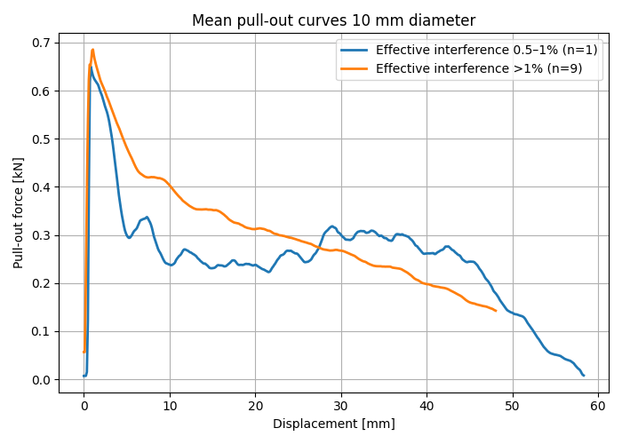
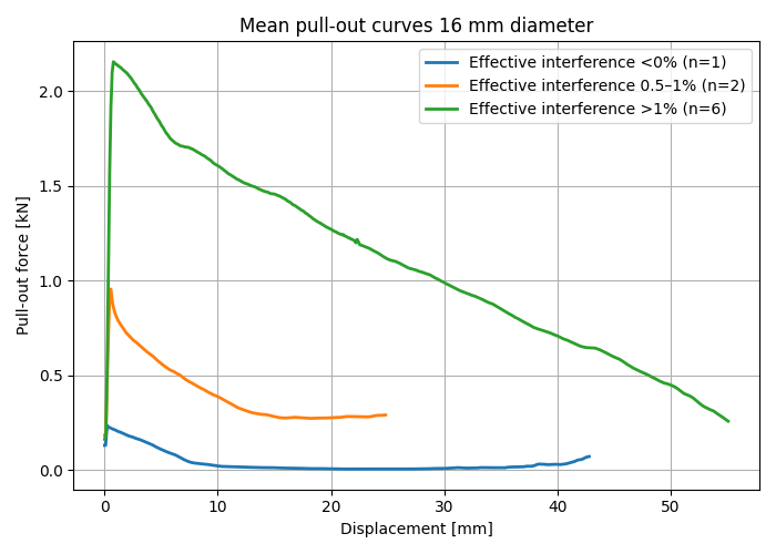
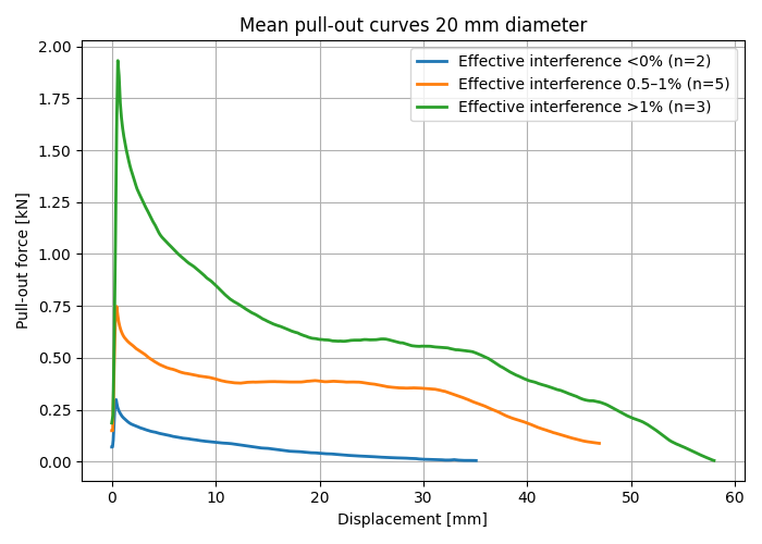
The graphs clearly show that all configurations exhibit a similar behaviour. This behaviour is characterised by an initial linear increase in load, followed by a peak representing the maximum push-out resistance, and subsequently a reduction in load with increasing displacement.
Influence of the effective interference level
The influence of the interference level is clearly visible in the load-displacement curves. For all diameters, the specimens with 1+% interference show a higher push-out resistance compared to those with a lower effective interference.
Table below presents the mean maximum push-out resistance together with the standard deviation (SD) and the coefficient of variation (CoV).
|
Dowel diameter [mm] (interference level) | Max push-out force [N] (SD.) | CoV | n |
|---|---|---|---|
| 10 (0.5–1%) | 664 (0) | 0.00 | 1 |
| 10 (>1%) | 898 (236) | 0.26 | 9 |
| 16 (0.5–1%) | 1071 (839) | 0.78 | 2 |
| 16 (>1%) | 2291 (350) | 0.15 | 6 |
| 20 (0.5–1%) | 869 (339) | 0.39 | 5 |
| 20 (>1%) | 2212 (218) | 0.10 | 2 |
For the 10 mm dowels, the variation in maximum push-out resistance is moderate for both 0.5-1% and 1+% interference levels. Also, no samples fell in the negative effective interference level. This indicates that, for this diameter, the tolerances have limited influence on the consistency of the results, although it does affect the magnitude of the push-out force.
In contrast, the 16 mm and 20 mm dowels exhibit considerably greater variability, suggesting that the connection response becomes increasingly sensitive to geometric variations, such as tolerances in dowel and hole diameters. Nevertheless, for all dowel diameters, the specimens with an effective interference level exceeding 1% consistently achieved a higher push-out resistance than those with lower interference levels.
The variation observed in the pull-out resistance values can be explained by the tolerances associated with the production of the pre-drilled holes. These holes were created using spade drills, which exhibit increasing dimensional tolerances as the drill diameter becomes larger. Measurements of the hole dimensions showed that, for all diameters, the actual hole sizes exceeded the target dimensions. As a result, the effective interference fit was lower than initially assumed.
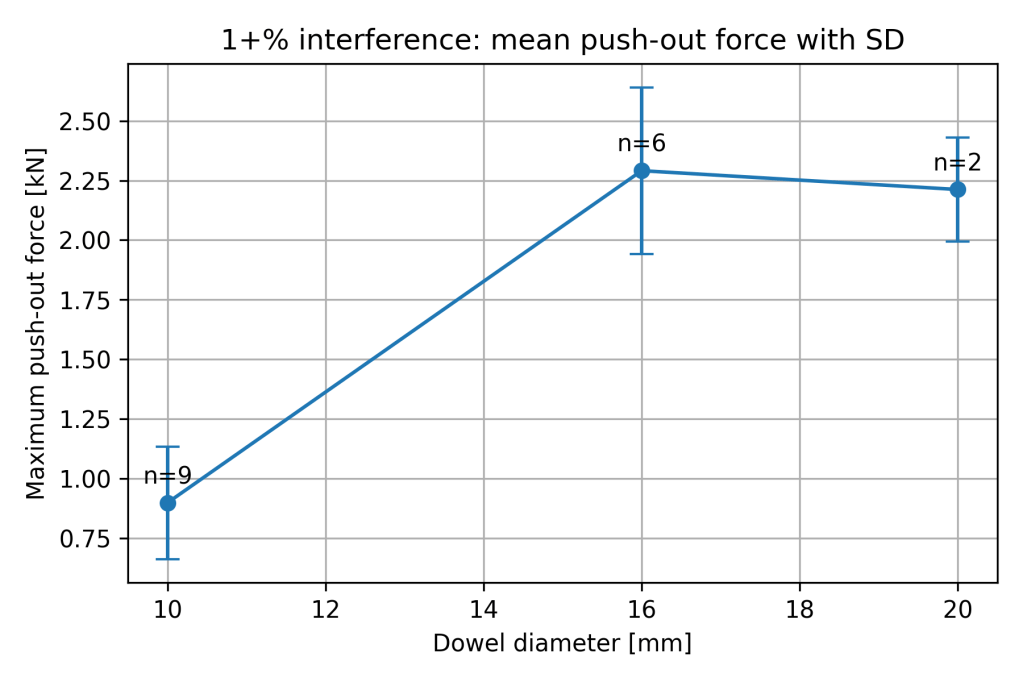
Influence of dowel diameter
The figure below shows the influence of dowel diameter on the push-out resistance. In this figure, only the results for 1+% interference are considered.
The results show an increase in push-out resistance from 10mm to 16mm diameter. However, a slight decrease in push-out resistance is observed from 16mm to 20mm.
Slip Modulus
To analytically determine the structural behaviour of a DLT beam using methods such as the gamma method (Eurocode 5, Annex B), it is necessary to determine the slip modulus per connector per shear plane. This was achieved through double-shear testing, as shown in the figure below.
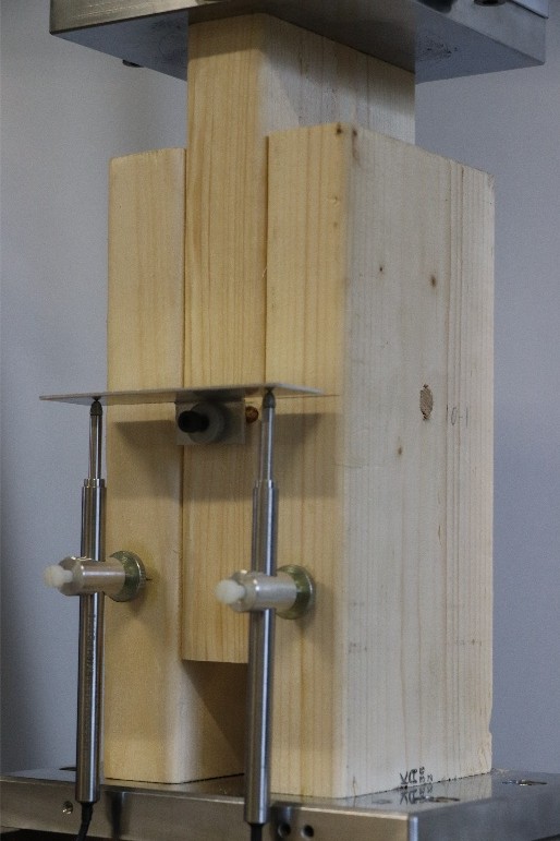
The slip modulus tests were conducted using a predefined loading protocol programmed into the Instron 5985 testing machine. In the first phase, the specimen was loaded up to 0.4Fmax, after which the load was maintained for 30 seconds. Subsequently, the specimen was unloaded to 0.1Fmax. After unloading, the samples were loaded again until failure. This initial phase was force-controlled to accurately follow the loading procedure prescribed in EN 26891.
The slip modulus is determined from the second loading phase of the procedure. It is calculated as the slope of the load–displacement curve between 0.1Fmax and 0.4Fmax. To determine the slip modulus per shear plane, it is necessary to divide by 2. This equation can be expressed as:
The experimentally determined slip modulus values are presented in the Table below and illustrated in the Figure below. As already observed in the load-displacement curves, a clear trend is present between increasing dowel diameter and increasing slip modulus. The mean slip modulus increases from 1.59 kN/mm for 10mm dowels to 4.80 kN/mm for 20mm dowels.
The variability in the results, expressed by the coefficient of variation (CoV), ranges between 0.10 and 0.23, indicating a relatively consistent behaviour. In addition, the standard deviation generally increases with dowel diameter, indicating a larger spread in the measured values for the larger dowels.
| Sample diameter [mm] | Mean slip modulus [kN/mm] | SD [kN/mm] | CoV | EC5 [kN/mm] |
|---|---|---|---|---|
| 10 | 1.59 | 0.16 | 0.10 | 3.74 |
| 12 | 2.13 | 0.31 | 0.15 | 4.49 |
| 14 | 3.02 | 0.57 | 0.19 | 5.24 |
| 16 | 3.86 | 0.46 | 0.12 | 5.99 |
| 18 | 4.72 | 1.07 | 0.23 | 6.74 |
| 20 | 4.80 | 1.01 | 0.21 | 7.48 |
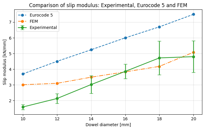
In addition, the Figure above includes the slip modulus values calculated according to Eurocode~5 for steel dowels. These values are determined based on the density of the timber and the dowel diameter and can be expressed as:
From the comparison, it can be observed that for all wooden dowels, the Eurocode expression overestimates the slip modulus. It should be noted that the Eurocode values are intended for steel dowels.
Failure mechanism
The Figure below shows the observed failure mechanisms in both the timber lamellae and the dowels.
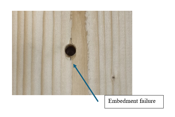
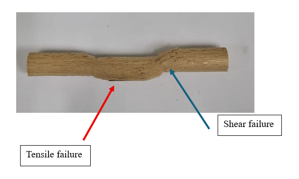
Embedment failure is observed in the timber, characterised by local crushing of the wood fibres surrounding the dowel. In addition, shear failure is observed in the dowels, while tensile failure is visible at the bottom side of the dowel.
The failure mechanism is therefore a combination of lamella embedment and dowel failure, which is consistent across all investigated diameters and agrees with the behaviour described by El-Houjeyri et al. (2019).
Full-scale Optimisation
The behaviour of the material and the dowel connection has now been investigated, with a particular focus on the rope effect and the slip modulus. The results obtained from these analyses enable the determination of the interaction between the individual lamellae, which in turn governs the global structural behaviour of the system.
In addition to evaluating the proposed dowel connection and its influence on the global behaviour of the full-scale beam, this part also focuses on the optimisation of the total volume and distribution of dowels along the beam length. The objective is to minimise the total amount of timber used while maintaining sufficient structural performance.
For this purpose, inspiration is drawn from composite steel–concrete beams. In the study by Lin et al. (2019), an optimal distribution of shear connectors was investigated for a simply supported composite beam subjected to a uniformly distributed load. In this study, a fixed number of connectors was assumed, and their distribution along the length of the beam was optimised to minimise deflection. The distribution was based on the slip along the beam, which is maximal near the supports and approaches zero at mid-span. Consequently, the connectors were distributed with a higher density near the supports and a lower density towards the mid-span, following either a linear (triangular) or a quadratic distribution. The results presented by Lin et al. (2019) demonstrate a clear improvement in structural performance for both distribution strategies.
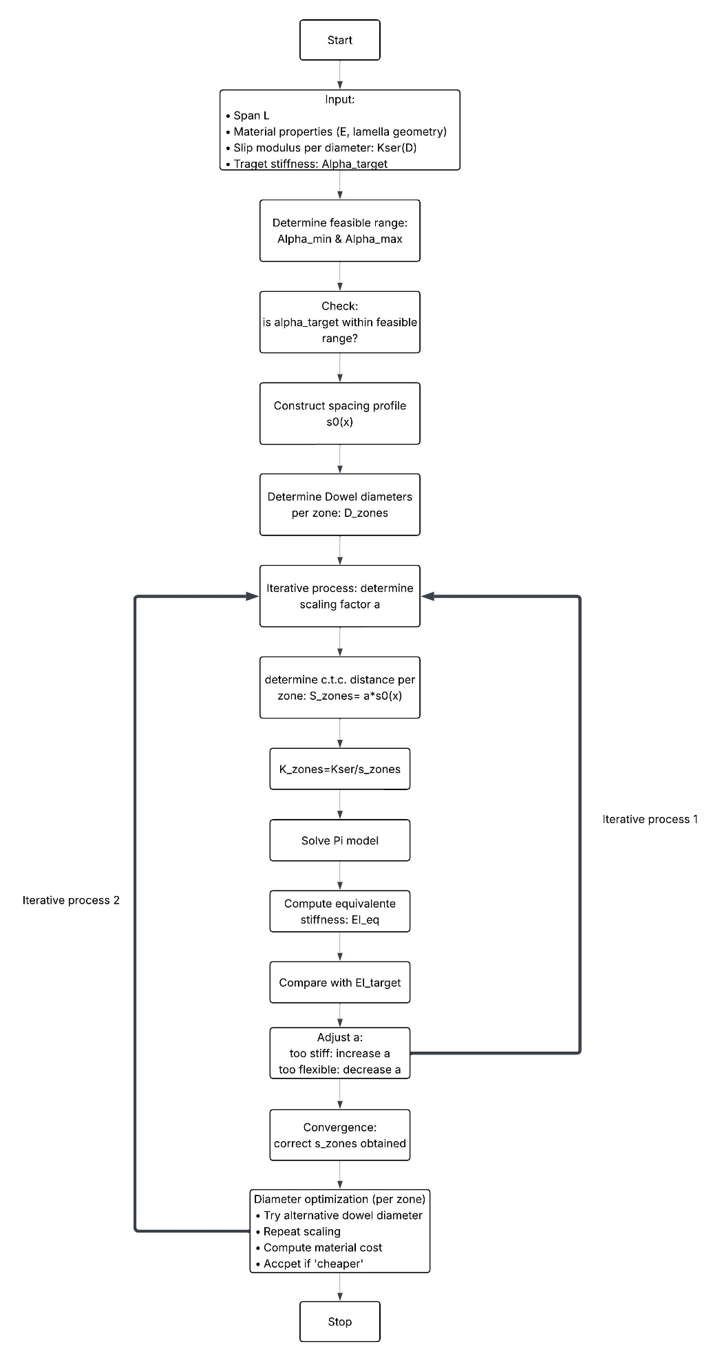
The overall optimisation procedure for the study in DLT beams, including the determination of connector spacing and dowel diameters, is illustrated in the flowchart below.
The Table below presents the results of the optimisation of the dowel distribution for a span of 2280 mm. The table includes the target stiffness factor, the corresponding target bending stiffness, the achieved bending stiffness, and the reduction in dowel volume relative to the configuration with the maximum achievable stiffness. For the given slip modulus, the maximum achievable stiffness can be achieved with 18 mm dowels with a centre-to-centre distance of 90 mm. For the considered cross-section, the maximum gamma factor is γ = 0.355. This results in a maximum stiffness factor of α= 0.427.
| α | Goal bending stiffness [Nmm2] | Achieved bending stiffness [Nmm2] | Mid-span deflection [mm] | Dowel volume reduction [%] |
|---|---|---|---|---|
| 0.20 | 3.260 × 10¹⁰ | 3.556 × 10¹⁰ | 9.895 | 80.71 |
| 0.30 | 4.889 × 10¹⁰ | 4.665 × 10¹⁰ | 7.543 | 66.05 |
| 0.35 | 5.704 × 10¹⁰ | 5.938 × 10¹⁰ | 5.925 | 45.21 |
The results show that, for all cases, the achieved bending stiffness closely matches the target stiffness. Furthermore, a significant reduction in dowel volume is observed. For example, a reduction in the stiffness factor from 0.427 to 0.36 (approximately -15%) results in a reduction in dowel volume of 45.21%.
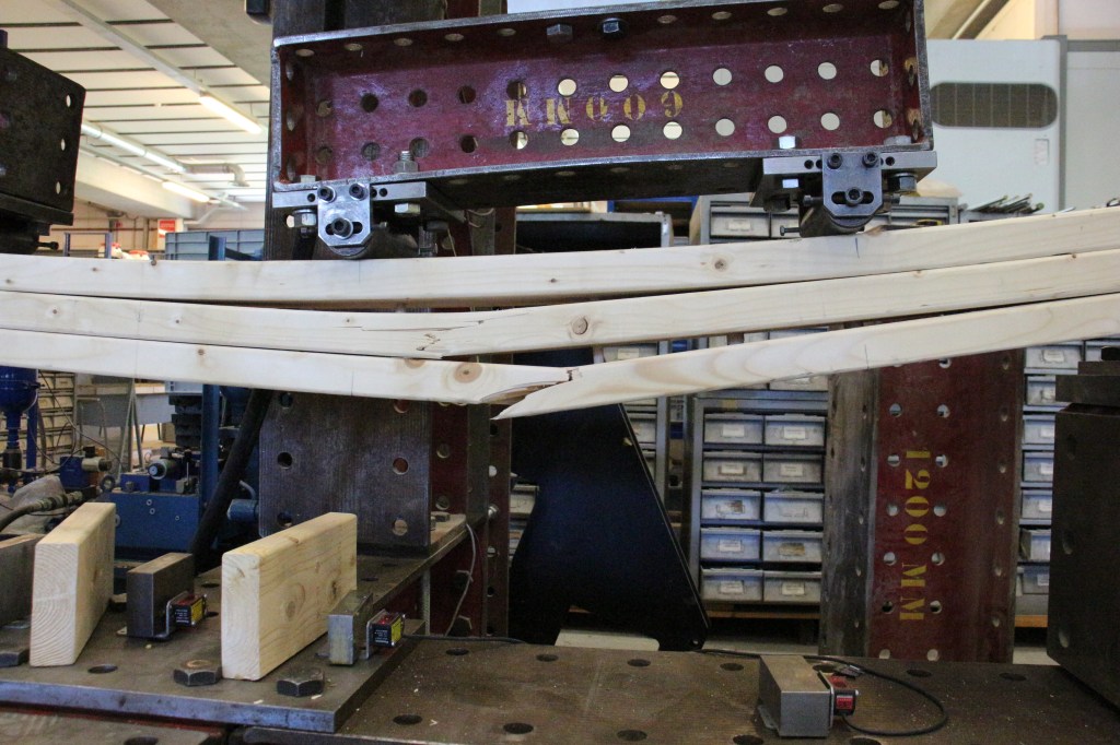
Six-point bending test
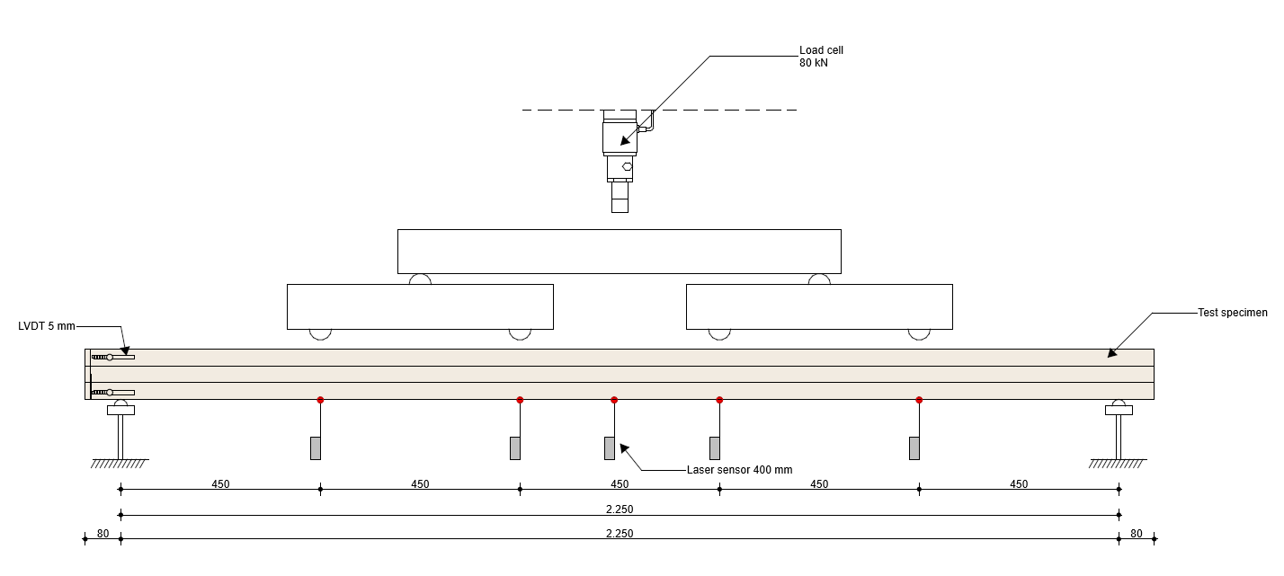
For the experimental testing, a 6-point bending test is employed. This configuration consists of four loading points, in contrast to the two loading points used in a conventional 4-point bending test. The main advantage of the 6-point bending setup is that it provides a closer approximation to a uniformly distributed load.
This is particularly relevant because the optimised results from the PI model are based on a simply supported beam subjected to a uniformly distributed load.
The experimental setup is shown in the Figure below. For the experimental 6-point bending test, the dowel configuration belonging to the beam with α=0.35 has been used.
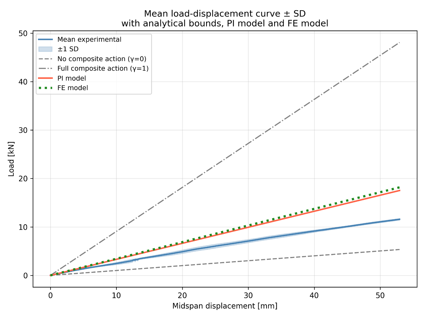
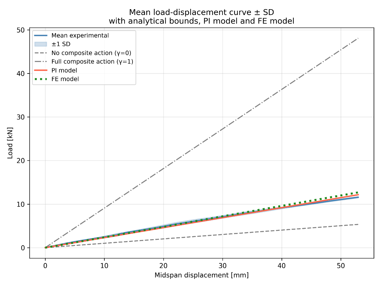
The figure below presents the mean linear portion of the load–displacement curve, including the standard deviation, the analytically determined boundary conditions, and the analytical and FEM results for the investigated beam. The analytical boundary conditions represent the cases of full composite action and no composite action, corresponding to a fully composite Glulam beam and three independent lamellae, respectively.
The bending stiffness is determined from the slope of the load–displacement curve between 0.1Fmax and 0.4Fmax. Using the analytical solution for displacement for a simply supported beam subjected to four equal point loads, the stiffness can be expressed as:
EI = 1.794 × 10¹¹ ⋅ k
This results in the following bending stiffness value:
EI = 4.11 × 10¹⁰ Nmm2 (CoV = 0.10)
In the graph, it can be observed that both the FE model and the analytical PI model overestimate the bending stiffness by approximately 44.5\%. This discrepancy can be attributed to the manner in which the slip modulus was experimentally determined.
In the experimental determination of the slip modulus, a symmetric loading configuration was used. In an actual beam subjected to bending, however, the dowels experience an asymmetric loading condition, in which the bottom lamella pushes the dowel outward while the top lamella pushes it inward. This results in a different local stress state and force transfer mechanism within the connection.
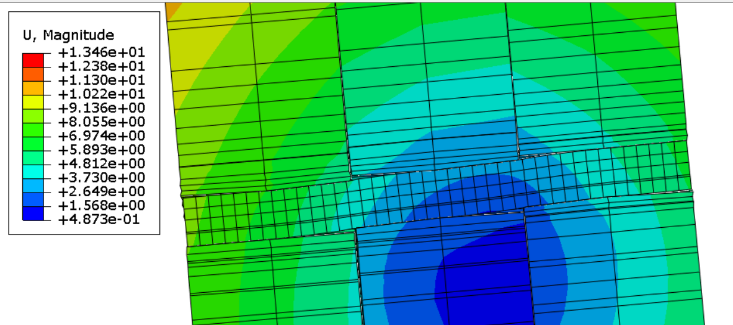
To investigate this effect, FE analysis was performed to determine whether a reduction factor could be introduced for the experimentally determined slip modulus. In the FE model, three timber lamellae were stacked together with a wooden dowel passing through all three layers. The boundary conditions were defined to reproduce the deformation behaviour observed during the six-point bending test. Consequently, the top lamella was displaced approximately 5mm outward, while the bottom lamella was displaced 5mm inward. By imposing displacements on both the upper and lower lamellae, rotation of the dowel was introduced without artificial restraints.
The slip modulus was subsequently determined from the relative displacement between the outer lamella and the middle lamella according to:
The Table below presents the slip modulus values obtained from the FE analyses for loading mechanism 1 (the experimental configuration used for slip modulus determination) and loading mechanism 2 (the loading configuration representative of a bending beam). The results demonstrate that the assumed loading mechanism significantly influences the slip modulus obtained from the numerical analyses.
| Diameter | Slip modulus mechanism 1 [kN/mm] | Slip modulus mechanism 2 [kN/mm] | Factor difference |
|---|---|---|---|
| 10 | 1.89 | 1.22 | 1.54 |
| 12 | 2.13 | 1.02 | 2.09 |
| 14 | 2.68 | 1.17 | 2.29 |
| 16 | 4.22 | 1.77 | 2.38 |
| 18 | 5.04 | 1.99 | 2.53 |
| 20 | 7.33 | 3.68 | 1.99 |
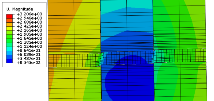
In addition to the reduction in slip modulus, the FE analyses revealed a transition in the dominant deformation mechanism of the dowel. For dowel diameters smaller than approximately 12mm, the dowels primarily deform in shear. This results in a characteristic S-shaped deformation pattern, as shown for the 10mm dowel in the Figure below. In contrast, larger dowels remain relatively straight and deform through a combination of shear and bending, thereby allowing rotational deformation of the connection. This behaviour is illustrated for the 12 mm dowel in the Figure on the right.
As a result, smaller dowels behave more similarly to the assumptions underlying loading mechanism 1, namely a connection loaded predominantly in shear. Consequently, the difference between the slip modulus obtained from loading mechanism 1 and loading mechanism 2 becomes smaller for slender dowels. This trend is confirmed by the assumption that can be made with the Johansen Meyer equation for single-loaded dowels.
Overall, the FE analyses demonstrate that the loading mechanism assumed during conventional slip modulus determination differs substantially from the actual loading mechanism occurring in a bending beam subjected to asymmetric loading. This difference leads to a reduced effective connection stiffness at beam level. For the dowel diameters used in the experimental beam tests (10, 16 and 18 mm), an average reduction factor of 2.14 was obtained.
Applying this reduction factor to the experimentally determined slip modulus results in excellent agreement between the analytically predicted and experimentally measured load–displacement responses, as shown in the Figure below. The analytically determined bending stiffness becomes:
EI = 4.1154 × 10¹⁰ Nmm2
Life Cycle Assessment (LCA)
It has been demonstrated that DLT beams can be regarded as mechanically connected composite beams. This composite action reduces bending stiffness compared to a fully composite beam, such as glued-laminated timber. Nevertheless, the DLT system can achieve structural performance levels comparable to those of conventional engineered wood products while eliminating the need for adhesives. Furthermore, it has been shown that a marginal reduction in bending stiffness, from α = 0.304 to α = 0.252, yields a reduction in dowel volume of 45%. This finding raises the question of whether this reduction in dowel material volume and adhesive use translates into a lower environmental impact over the full life cycle of the product.
To address this question, a Life Cycle Assessment is conducted. An LCA is a standardised methodology for quantifying the environmental impact of a product or system across its entire life cycle, from raw material extraction to end-of-life processing. This approach enables the comparison of multiple systems based on their environmental performance.
The optimised DLT configuration and DLT beams with a uniformly distributed dowel arrangement are compared with glulam, NLT, and structural steel beams with an equivalent stiffness or strength. The inclusion of steel provides a broader reference frame and allows for an assessment of absolute environmental savings. The comparison is based on the Global Warming Potential (GWP), expressed in kg CO2-equivalent per functional unit.
The comparison of the environmental impact between the different products is carried out using Environmental Product Declarations (EPDs). “An EPD provides quantitative, objective, and verified information about the environmental impact of a product over its entire life cycle, from raw material extraction to end-of-life processing” (EPD International, n.d.).
In Environmental Product Declarations, the life cycle is divided into several stages, ranging from raw material extraction to the end-of-life stage. These stages are schematically illustrated in the Figure below (reproduced from Lemperos (2024)).

For the LCA comparison, the system boundaries are defined as cradle-to-gate with end-of-life stages (A1-A3 and C1-C3). These boundaries are consistent with the system definitions used in the selected EPDs.
Inventory
The following beam systems were compared:
Optimised DLT configuration (beam length: 2280 mm):
Optimised DLT corresponding to a stiffness factor of α = 0.35
Glulam: GL24h, 80 × 140 mm (width × height), representing the smallest cross-section that satisfies the required bending moment resistance
NLT: 3 lamellae connected with 8 mm screws at a centre-to-centre spacing of 95 mm
Steel beam: IPE 100, representing the smallest cross-section that satisfies the required bending moment resistance
Uniform dowel distribution:
In this comparison, the maximum commercially available cross-section of standard sawn timber was used as a reference. Based on this cross-section, the limiting uniformly distributed loads ((q_{lim})) were determined for beam spans of 4 m, 6 m, and 7.5 m. Subsequently, an equivalent glulam cross-section capable of resisting the same (q_{lim}) was selected. This glulam section was then used as the reference for determining the corresponding DLT, NLT, and steel beam cross-sections.
Glulam: 120 × 280 mm (width × height)
DLT: 10 lamellae, each measuring 120 × 38 mm (width × height), connected with 18 mm dowels at a centre-to-centre spacing of 90 mm
NLT: 9 lamellae, each measuring 120 × 38 mm (width × height), connected with 8 mm screws at a centre-to-centre spacing of 56 mm
Steel beam: IPE 180
Results
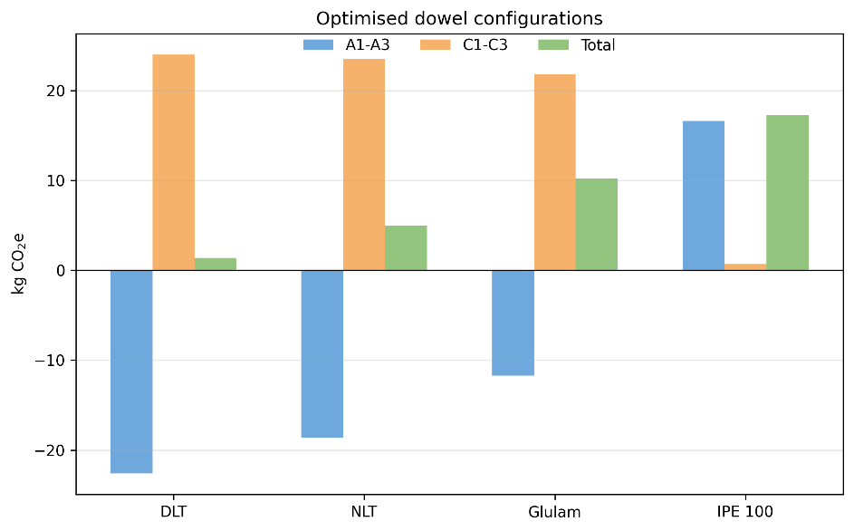
This resulted in the following outcomes for the comparison of the optimised dowel configuration.
| Beam type | A1–A3 (Total kg CO₂e) | C1–C3 (Total kg CO₂e) | Cradle-to-grave (Total kg CO₂e) | Cradle-to-grave (kg CO₂e/m) |
|---|---|---|---|---|
| DLT (α = 0.35) | -22.6 | 24.0 | 1.39 | 0.61 |
| NLT | -18.6 | 23.5 | 4.98 | 2.18 |
| Glulam | -11.7 | 21.8 | 10.2 | 4.47 |
| IPE 100 | 16.6 | 0.693 | 17.3 | 7.59 |
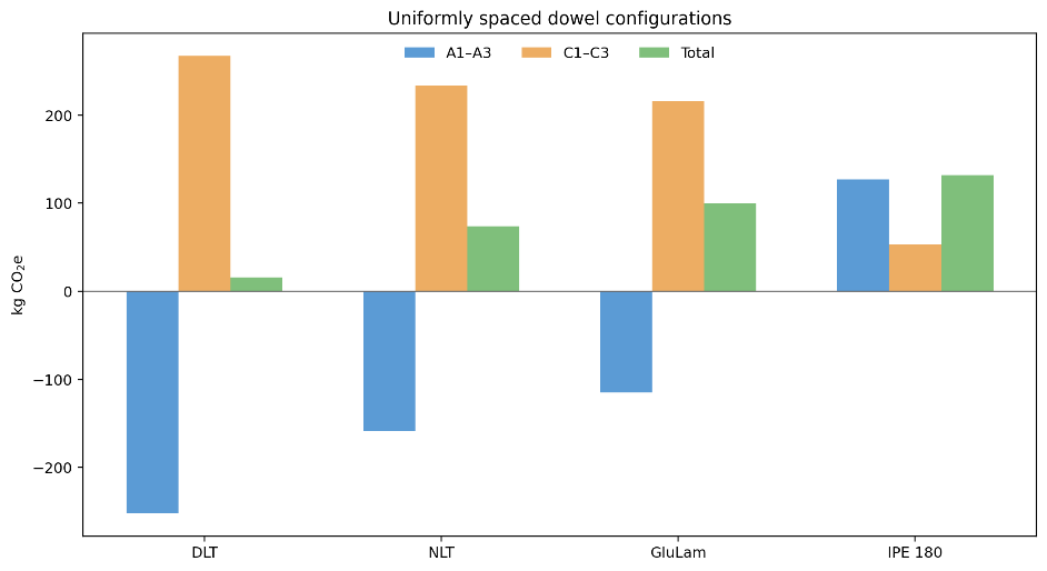
And for the beam comparison with uniformly divided dowels.
| Beam type | A1–A3 (Total kg CO₂e) | C1–C3 (Total kg CO₂e) | Cradle-to-grave (Total kg CO₂e) | Cradle-to-grave (kg CO₂e/m) |
|---|---|---|---|---|
| DLT | -252.0 | 267.0 | 15.7 | 2.09 |
| NLT | -159.0 | 233.0 | 74.0 | 9.86 |
| Glulam | -115.0 | 216.0 | 100.0 | 13.4 |
| IPE 180 | 127.0 | 52.9 | 132.0 | 17.6 |
Absolute results for the 7.5 meter beam
Conclusion
This study showed that the hygroscopic swelling of wooden dowels generates measurable pull-out resistance. However, the large variability between specimens meant that this effect could not reliably be included in structural design. Tests on connection stiffness demonstrated that both slip modulus and load-carrying capacity increase with dowel diameter.
Full-scale six-point bending tests confirmed that DLT beams behave as a composite beam, with the bending stiffness strongly dependent on the stiffness of the dowel connections. While the experimentally observed composite action was lower than predicted from connection-level tests, the bending moment capacity remained comparable to that of a fully composite beam. This indicates that serviceability requirements, particularly deflection, are more critical than ultimate bending resistance in DLT beam design.
The environmental assessment showed that DLT consistently achieved the lowest cradle-to-grave global warming potential compared with Glulam, NLT, and steel beam alternatives. Optimising the dowel configuration reduced dowel material use by approximately 45%, but this resulted in only a modest 2.6% reduction in CO₂-equivalent emissions. Nevertheless, the findings demonstrate that DLT is both a structurally viable and environmentally attractive alternative to conventional beam systems.
Limitation and recommendation
As this research was an exploratory study, several recommendations are made for future work. First, a larger number of test specimens should be used to enable the determination of characteristic design values. While the five specimens per configuration used in this study were sufficient for exploratory research, they are insufficient for statistical characterisation.
Further validation of the developed analytical models requires additional full-scale beam tests. Future studies should investigate a wider range of beam configurations, including different span lengths, numbers of lamellae, and dowel layouts. Testing fully composite and non-composite reference beams is also recommended to quantify the influence of the experimental setup.
The manufacturing process should be improved through the use of CNC-controlled woodworking machinery. The results showed that the performance of the dowel connection is highly sensitive to manufacturing tolerances, particularly in the dimensions of the pre-drilled holes.
Several long-term effects also require further investigation. The connection mechanism relies on hygroscopic swelling of the wooden dowels, but wood can relax under sustained stress, potentially reducing contact pressure and pull-out resistance over time. Future research should quantify this effect and directly measure contact pressure at the dowel–timber interface. In addition, the influence of fluctuating temperature and humidity conditions should be studied, as these may affect the long-term performance of the connection.
Finally, the environmental assessment should be expanded to include the impact of manufacturing processes and the end-of-life benefits represented by Module D. This would provide a more complete understanding of the sustainability performance of DLT systems.
References
Bergsagel, D., Heisel, F., Owen, J., & Rodencal, M. (2025). Engineered wood products for circular construction: a multi-factor evaluation of lamination methods. Npj Materials Sustainability, 3(1). https://doi.org/10.1038/s44296-025-00067-7
De Moraes Pereira, M. C., Sohier, L. a. P., Descamps, T., &Calil, C., Junior. (2021). Doweled cross laminated timber: Experimentaland analytical study. Construction and Building Materials, 273, 121820.https://doi.org/10.1016/j.conbuildmat.2020.121820
El-Houjeyri, I., Thi, V., Oudjene, M., Khelifa, M., Rogaume, Y., Sotayo, A., & Guan, Z. (2019). Experimental investigations on adhesive free laminated oak timber beams and timber-to-timber joints assembled using thermo-mechanically compressed wood dowels. Construction and Building Materials, 222, 288–299. https://doi.org/10.1016/j.conbuildmat.2019.05.163
EPD International. (n.d.). EPD International. https://www.environdec.com/home
Hussin, M. H., Latif, N. H. A., Hamidon, T. S., Idris, N. N., Hashim, R., Appaturi, J. N., Brosse, N., Ziegler-Devin, I., Chrusiel,
L., Fatriasari, W., Syamani, F. A., Iswanto, A. H., Hua, L. S., Edrus, S. S. a. O. A., Lum, W. C., Antov, P., Savov, V., Lubis, M. a. R.,
Kristak, L., . . . Sedliačik, J. (2022). Latest advancements in high-performance bio-based wood adhesives: A critical review. Journal of Materials Research and Technology, 21, 3909–3946. https://doi.org/10.1016/j.jmrt.2022.10.156
Lemperos, X. (2024, February 6). The stages of LCA. Nordic BIM Group Norge. https://anavitor.ai/en/ecobuild-lca-perspectives-for-the-built-environment/the-stages-of-lca
Lin, J., Wang, G., & Xu, R. (2019). Particle swarm Optimization–Based Finite-Element analyses and designs of shear
connector distributions for Partial-Interaction composite beams. Journal of Bridge Engineering, 24(4). https://doi.org/10.1061/(asce)be.1943-5592.0001371
Liu, R., Yao, L., Gong, Y., & Wang, Z. (2025). Life Cycle Assessment with Carbon Footprint Analysis in Glulam Buildings: A Review. Buildings, 15(12), 2127. https://doi.org/10.3390/buildings15122127
Lu, Y., Xie, W., Wang, Z., & Gao, Z. (2018). Shear stress and interlaminar shear strength tests of cross-laminated timber beams. BioResources, 13(3), 5343–5359. https://doi.org/10.15376/biores.13.3.5343-5359
Sotayo, A., Bradley, D. F., Bather, M., Oudjene, M., El-Houjeyri, I., & Guan, Z. (2020). Development and structural behaviour of adhesive free laminated timber beams and cross laminated panels. Construction and Building Materials, 259, 119821. https://doi.org/10.1016/j.conbuildmat.2020.119821
Yeh, Y., Yeh, Y., Yeh, Y., & Yeh, Y. (2024). Bending behaviour and failure modes of Non-Glue-Laminated timber beams composed of wooden dowels and Self-Tapping screws. Buildings, 14(2), 394. https://doi.org/10.3390/buildings14020394
