Development of an analytical model to predict horizontal capacity
Article by : Mees Fabel
Supervisors : Arjan Habraken, Akke Suiker, Nischal Pradhan
Natural disasters are constantly occurring in the Philippines, think of earthquakes, typhoons, landslides, floodings. Because of this, millions of people have uncertain living conditions. Some people are able to build a house which can withstand earthquakes and typhoon winds, but it is unaffordable for most. The conventional system that is used for these houses in the Philippines is concrete hollow block shear walls, which are reinforced with embedded rebars and then infilled with mortar.
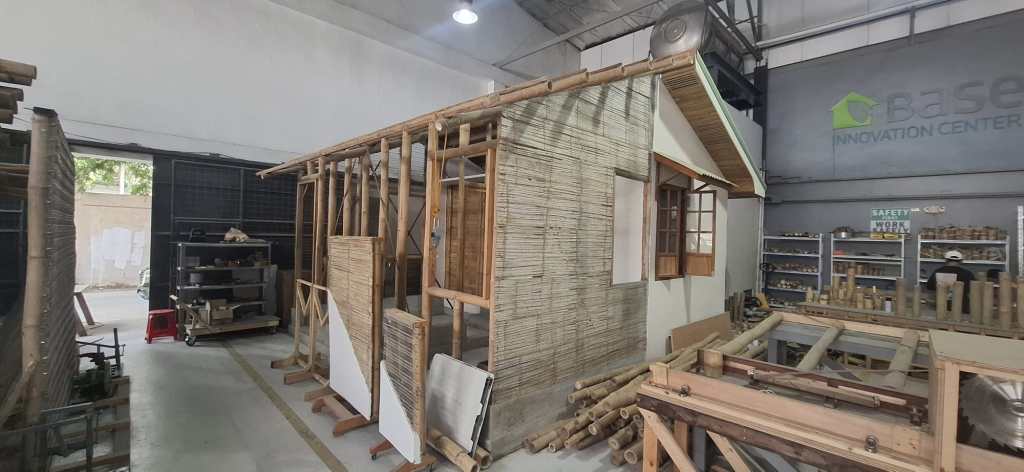
Composite Bamboo Shear Walls (CBSWs) are a promising alternative to this conventional shear wall system, not only in the Philippines but in all tropical regions where bamboo is abundant. However, the structural behavior and design capacity are not yet well established. This article contains a short overview of the work done in my graduation thesis. The thesis investigates the predictability of horizontal shear capacity of CBSW by comparing outcomes of experimental testing and analytical modeling. Two configurations of 2.4 × 2.4m wall panels were subjected to monotonic and cyclic in-plane loading to characterize global force–displacement behavior and failure mechanisms. In parallel, single-fastener tests were conducted to quantify the nonlinear behavior of these fasteners.
CBSW configuration
A CBSW panel consists of a bamboo–timber frame with vertical bamboo culm studs nailed to top and bottom timber beams. The studs are anchored to the foundation with embedded rebar and tied to the top beam with J-bolts, both strengthened with mortar infill. A matrix of either rib lath (steel mesh) or tadtad (flattened bamboo mats) is nailed to the frame and subsequently covered on one side with a two-coat mortar plaster to form the cladding. Optional steel flat-bar bracing may be included for temporary stability during transport, depending on panel size and configuration.
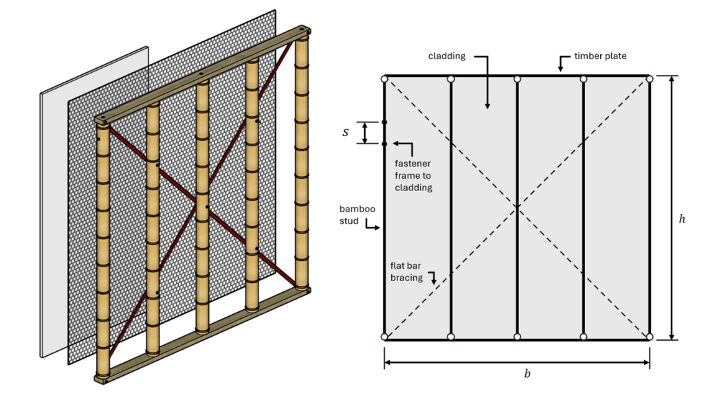
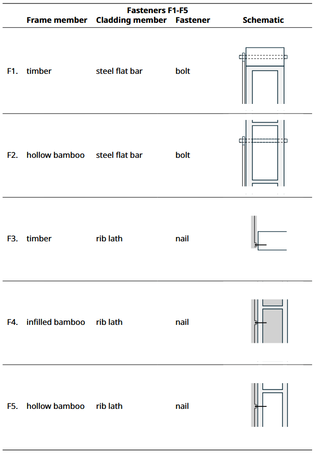
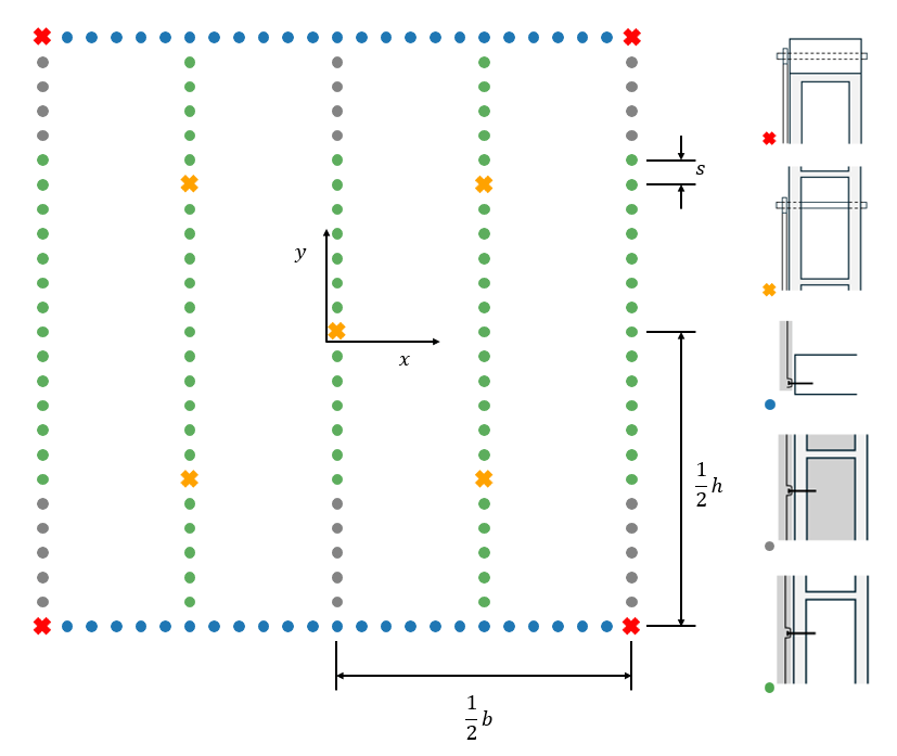
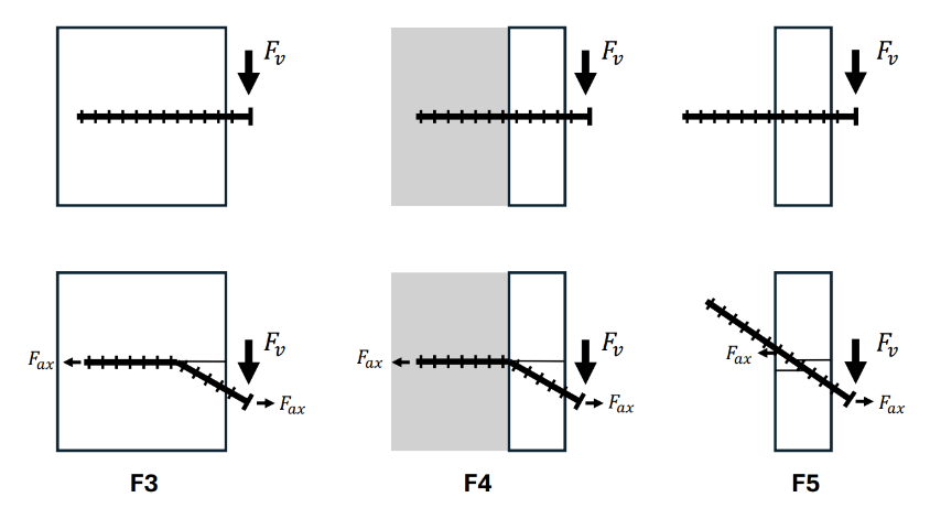
The connections between frame and cladding are the fasteners. There are a total of 5 fastener types used in this wall system. Included in this article is a table explaining the fasteners and which elements of the shear wall they connect. This table also includes a cross-section showing the location of the fastener.
CBSW model
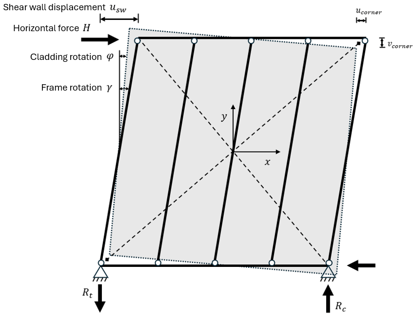
A model was developed to give an accurate representation of the real behavior of the shear wall. Previous research shows that for framed timber structures, where the main elements are frame and cladding, failure of the shear wall is determined by the behavior of the cladding-to-frame fasteners. When a horizontal force is applied in-plane at the top left corner, the frame will start to deform. The rigid cladding, connected to the frame by fasteners, starts to rotate about its center. These separate movements of frame and cladding cause individual deformations of the fasteners, which can be calculated. By considering the stiffness of each fastener, a fastener force and additionally a shear wall force can be derived.
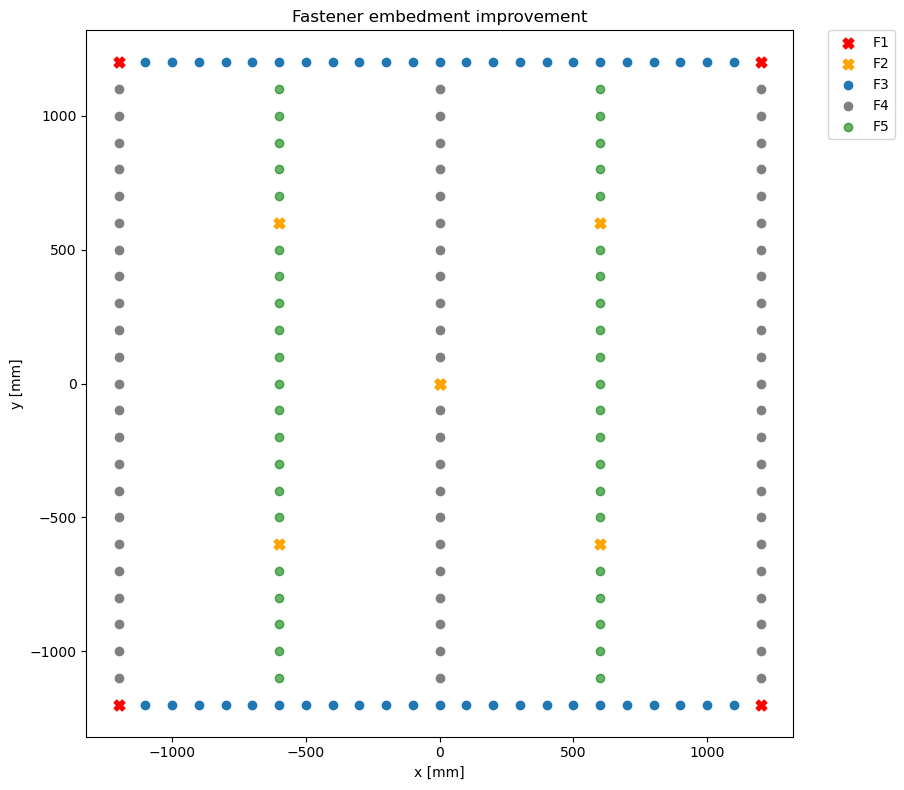
A model has been set up that uses the logic from the mechanical behavior. The model only considers the position of the fasteners, and their relative displacements. Each fastener type has its own behavior and material properties. Most of these properties have been retrieved from literature, but for two fastener types (F4 & F5) properties were determined through experimental testing. The next figure shows a schematic overview and spacing of the fastener types in a CBSW panel. At the right side is an overview of the fastener connections.
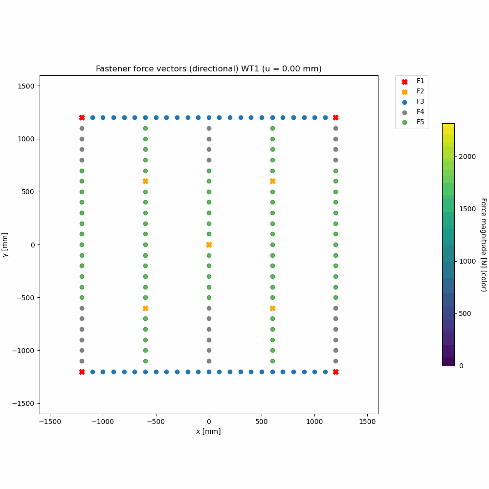
The capacity of the wall can be determined by incrementally increasing the displacement of the shear wall. This causes an increase in the relative displacement of the fasteners, and the stiffness and capacity of the fasteners can be determined. Featured below is a visualization of the modeled behavior, showing the direction and magnitude of forces on each fastener.
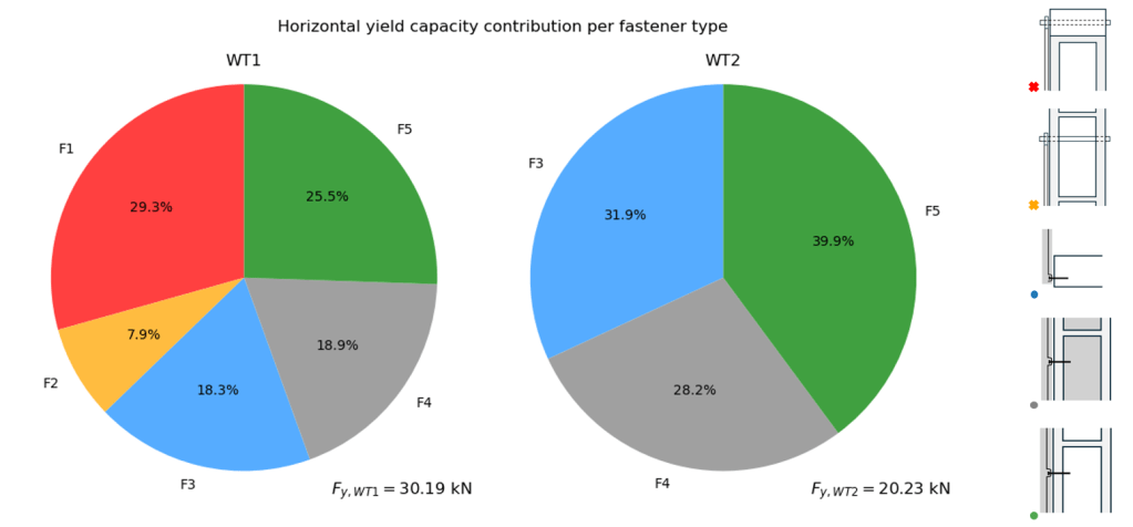
The model also gives an insight in the force distribution per fastener type. See above figure for an overview of the fastener forces per fastener type at yielding, both for a wall with (WT1) or without (WT2) flat bar bracing. See also the figure displaying the wall configurations.
Experimental testing
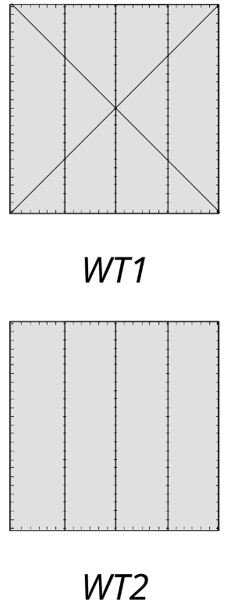
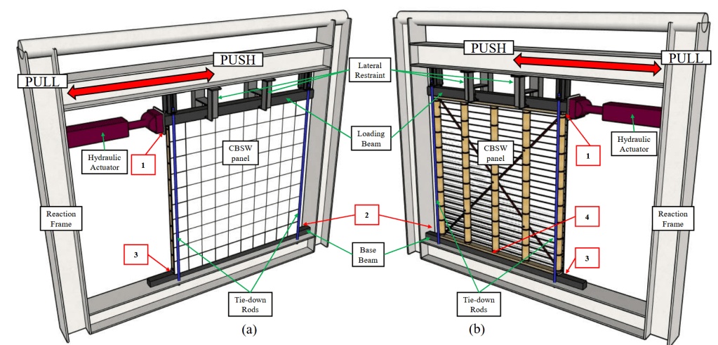
A total of 12 tests were conducted: 1 monotonic and 5 cyclic tests for two different shear wall configurations, one with flat bar bracing (WT1) and one without (WT2). See the adjacent figure for a quick overview of the different configurations.
The shear performance of the CBSW panels was evaluated using a reaction-frame setup in which the specimen was placed inside a stiff testing frame to prevent sliding and uplift. Lateral loads were applied through a hydraulic actuator connected to a loading beam at the top of the wall, ensuring uniform force transfer. Out-of-plane restraints and tie-down rods controlled uplift and overturning while allowing in-plane shear behavior to develop. Displacements were recorded using LVDTs and draw-wire sensors to capture lateral drift, overturning effects, and central panel deformation. See the figure for an overview of the test setup.
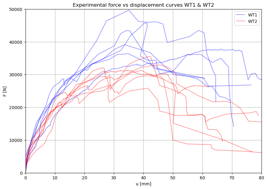
Testing resulted in a good overview of CBSW behavior. Featured below are a video of the cyclic testing and a graph containing the force-displacement envelopes of all the tests.
Comparison of results
See the figure displaying the force-displacement diagrams of the predicted and experimental results.
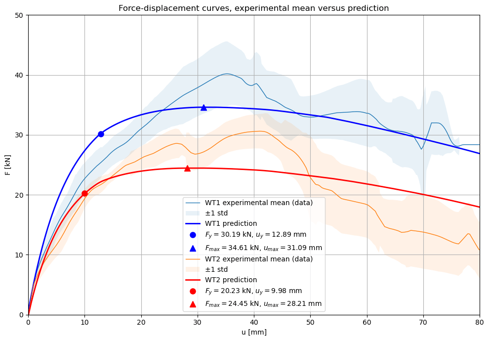
The numerical model produces force–displacement curves for both wall types, which are compared to the experimental mean responses. The model captures the effect of bracing well, showing clear and proportionally accurate capacity differences between WT1 and WT2. However, the initial stiffness is overestimated, particularly for WT1, likely due to assumed bolt stiffness values and possible unaccounted fastener slip in the experiments. The model also underestimates the maximum load and smooths the pronounced peak observed experimentally. For WT2, the post-peak capacity decay is less steep in the model, as the improved post-peak coherence provided by flat-bar bracing (this was only observed experimentally) is not represented in the numerical formulation.
Exploration of design improvements with model
In this research, the goal of shear wall improvements is to reach a higher horizontal shear capacity. This can be achieved by increasing the stiffness of the system, increasing the capacity of individual fasteners, or reducing the rate of damage accumulation. The model can be used to implement possible improvements to CBSW, without having to rely on experimental testing. This is especially useful in the assessment of the improvement ideation process. The geometry and fastener properties can be altered as
a means to change the stiffness or capacity of the total system. Three improvement options are presented in this section, and applied in the model thereafter so that the potential can be assessed. The three improvement options all concern a different component of the CBSW system.
Option 1
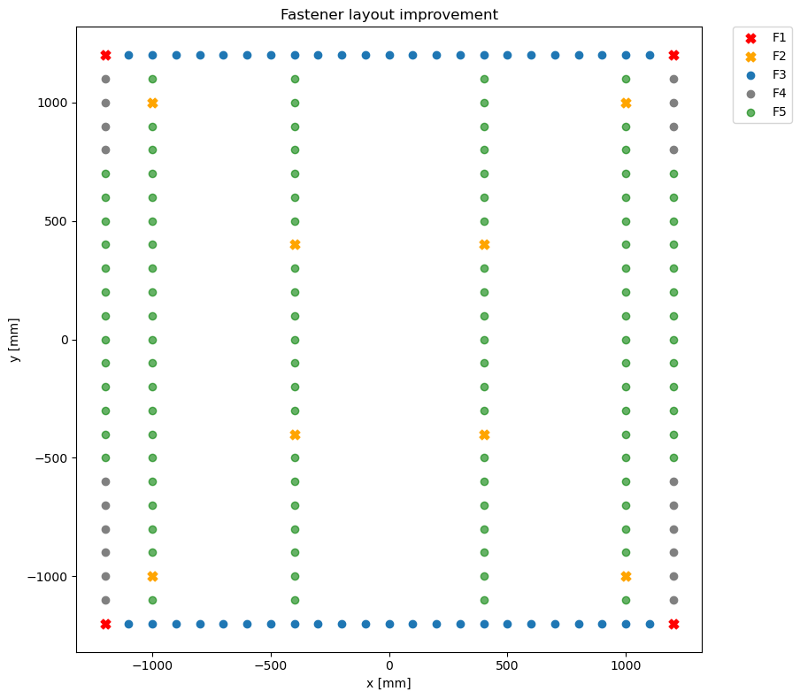
See the fastener configuration displayed in the figure above. Analysis of the fastener force distribution shows that fasteners near the center of the shear wall contribute little to load transfer, while those near the corners are highly engaged. An improved configuration was therefore developed by relocating studs closer to the wall edges and removing the central stud, while maintaining a maximum stud spacing of 600 mm to ensure adequate cladding support. Due to geometric constraints of the rib lath used in the cladding, additional intermediate timber beams were not feasible. The resulting configuration consists of six studs, with increased fastener density at the edges where deformations are largest. This arrangement adds 23 fully engaged fasteners and is expected to increase the overall shear capacity of the wall.
Option 2
Modifying the shear wall configuration can be impractical in some cases, prompting consideration of less intrusive improvement measures. One such option is to increase the number of fasteners embedded in mortar infill by fully infilling the edge and center studs, replacing the standard non-infilled fasteners at those locations. Since infilled nodes are already required at the top and bottom of these studs, this adjustment can be implemented with minimal additional effort. The measure is expected to increase the initial stiffness of the shear wall due to the higher elastic stiffness of the infilled fasteners. However, its effect on overall shear capacity is uncertain, as these fasteners exhibit a more rapid post-peak capacity decay, which may lead to earlier strength loss when concentrated along the highly deforming wall perimeter.
Option 3
The fasteners used in the shear wall currently rely on smooth common wood nails, which, despite their availability, provide limited capacity due to their low strength and tendency to lose traction under deformation. Once yielding occurs, smooth nails are particularly susceptible to pull-out, and the use of screws is not suitable because of the high risk of splitting the bamboo. An effective alternative is the use of ring shank nails, which feature a profiled surface that enhances mechanical interlock with the embedment material. Unlike smooth nails, ring shank nails can develop axial resistance, which contributes to an increased shear capacity through the rope effect. This axial contribution can be accounted for in the model, resulting in a notable increase in overall fastener capacity.
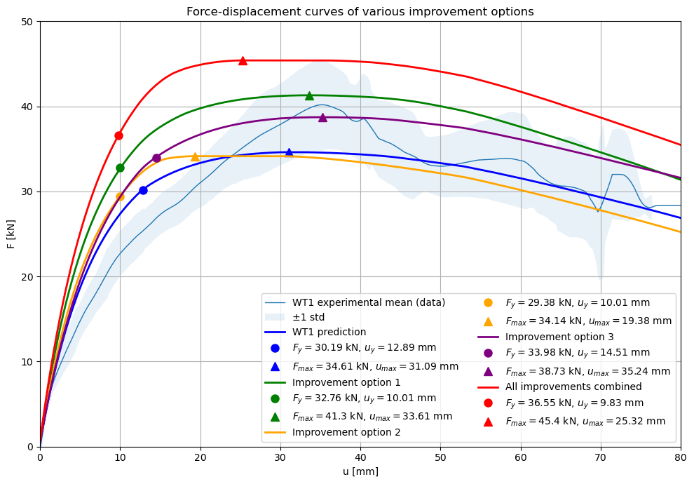
The figure above demonstrates the effect of the improvements by applying them in the shear wall model. It becomes clear that improvement option 1 and 3 have the biggest impact on capacity, while option 2 only influences the stiffness of the wall panel. Additionally, a last force-displacement curve is included which combines all three of the improvement options to achieve the maximum capacity for this size and configuration of shear wall.
Conclusions
- The analytical model shows good agreement with experimental results for both WT1 and WT2, with force, displacement, and stiffness predictions generally within 10–20% error, validating its use for arbitrary shear wall configurations.
- Analysis of fastener force distribution reveals that corner fasteners govern shear resistance, while fasteners near the wall center contribute minimally, highlighting clear opportunities for structural optimization.
- Among individual improvement strategies, reconfiguring the wall layout (Option 1) and enhancing fastener properties with ring shank nails (Option 3) yield the most significant increases in shear capacity, whereas increasing mortar embedment (Option 2) mainly improves stiffness with limited capacity gains.
- Combining all proposed improvements in the model results in a substantially enhanced CBSW panel, characterized by higher stiffness, higher yield and peak forces, and a more pronounced plastic response, demonstrating the model’s effectiveness as a design and optimization tool.
- Comparison of horizontal shear capacity per meter shows that the current design value is highly conservative, underestimating experimental and model-based capacities by at least a factor of 2.8, indicating significant potential for more efficient and accurate design of Composite Bamboo Shear Walls.
