Structural and Environmental Evaluation of Optimized Dowel Configurations in Adhesive-Free DLT Beams compared to Glulam and NLT
Article by : Bonno van der Horst
Supervisors : Arjan Habraken
DLT is an Engineered Wood Product (EWP) in which, unlike more common systems such as Glulam or Nailed Laminated Timber (NLT), no adhesives or steel fasteners are used. Instead, kiln-dried wooden dowels are applied, which will expand due to the ambient climate. This approach is expected to improve recyclability and reduce the use of chemical substances.
In the initial phase of this research, detailed investigations are carried out on both the micro and meso scale.
Micro scale: the pull-out strength of expanded timber dowels is tested (as shown in the first image).
Meso scale: the effective slip modulus is determined (second image). The slip modulus (Kser) describes the relative deformation between timber lamellas under load, in other words, the stiffness of the connection between the lamellas. This parameter can be used to analytically determine the strength of mechanically connected beams by calculating the effective bending stiffness using the gamma method.
Ultimately, this research will conclude with a full-scale test (macro scale), where an entire beam length is tested using an optimized dowel configuration in terms of material efficiency and structural performance. The outcomes will be complemented with a life cycle assessment (LCA) and compared against Glulam and NLT beams of the same span.
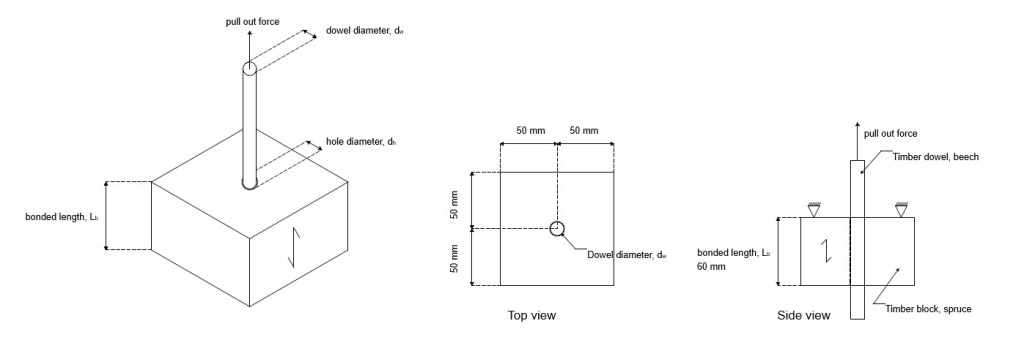
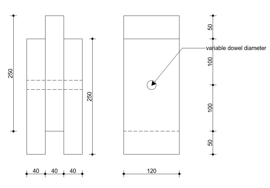
A wooden dowel (beech) is first kiln-dried and then placed into a pre-drilled hole with the same diameter as the oven-dry dowel. This is done in a timber block made of the same material as the lamellas (spruce). As the dowel acclimatizes, it absorbs ambient moisture, expands, and creates a tight fit.
During the test, the dowel is pulled out of the timber block, resulting in a force–displacement diagram. From this curve, the clamping force of the connection can be determined.
Using this test setup, in which a force is applied vertically onto the middle lamella, a force–displacement diagram can be obtained. From these results, the slip modulus (Kser) can be determined. This parameter can then be used to analytically calculate the strength of a mechanically connected beam.
Testing Phase
Pull out test (micro scale)
First, testing was conducted at the micro scale. In this phase, the clamping force resulting from the tight-fit connection was investigated, which is determined by the following equation:
Fpull=μpAc=μp(πDL).
In this equation, μ represents the coefficient of friction between the dowel and the bore wall (wood–wood contact), p denotes the contact stress between the dowel and the bore wall, D is the nominal diameter of the bore, and L is the bond length, which was 58 mm for all specimens.
In addition to the clamping force, the optimal oversize was investigated in order to achieve a manufacturable and mechanically robust connection. The selected oversize is based on the theoretical assumption that the beechwood dowels tend to swell, causing them to press against the bore wall of the spruce wood. This interaction generates hygroscopic stress (p), which can be approximated as follows:


For example, 3% oversize =
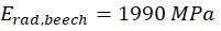
(Hering et al., 2011)
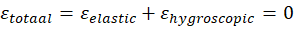
Only hygroscopic stresses:
Rad: 59.7 Mpa
Tang: 20.4 Mpa
However, the stress never increases to such an extent. During the development of this stress, the following limitation is encountered: the maximum compressive stress perpendicular to the grain of spruce wood is approximately 2.5 MPa, whereas for beech wood it is approximately 8.3 MPa. Consequently, it is expected that the contact stress between the dowel and the bore wall increases up to 2.5 MPa, after which it will deform as plastic deformation. As a result, the bore hole deforms to the shape of the dowel, but no additional force can be transferred.
Based on this approximation, a theoretical oversize of 0.4% would be sufficient. However, for reasons of manufacturability, an oversize of 1% was selected. In addition to the 1% oversize, a 3% oversize was also investigated to evaluate whether a larger oversize would result in a higher clamping force. For this test, three nominal diameters were examined: 10 mm, 16 mm, and 20 mm.
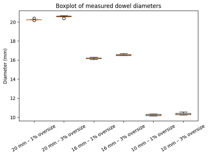
The dowels were rotated manually with a lathe, which introduces a degree of inaccuracy that is visible in the graph below. It can be observed that larger nominal diameters allow for more accurate machining, as the absolute dimensional values are spaced further apart. Consequently, the 10 mm dowels exhibit greater variation in oversize compared to the other two diameters. In addition to the manual machining process, measurement procedures may also contribute to the observed inaccuracies.
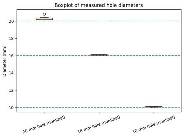
In addition to the variation in the cross-sectional dimensions of the dowels, variation is also present in the diameters of the bores. The bores in the wood were produced using a spade drill bit mounted in a drill press. Achieving the exact nominal diameter during drilling is challenging, for example due to slight misalignment of the drill bit or runout during drilling. The measured bore diameters are presented in the graph below. From this graph, it can be observed that smaller diameters can be drilled with greater accuracy.
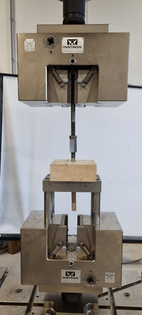
Five specimens were produced for each configuration, resulting in a total of 30 specimens. These specimens were subjected to a pull-out test, which was converted into a push-out test for practical reasons. In this setup, a force is applied to the bottom of the dowel, thereby pushing the dowel out of the bore, as illustrated in the picture on the right.
From these tests, force–displacement diagrams were obtained. The maximum force peak corresponds to
where is the expected contact stress of 2.5 MPa and is an unknown coefficient of friction, which according to theory is expected to lie between 0.1 and 0.6. It was therefore anticipated that the pull-out force would increase with increasing nominal diameter, i.e., with increasing contact area. Furthermore, no difference in pull-out force was expected between the 1% and 3% oversize configurations.
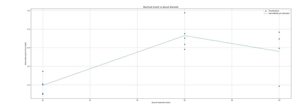
However, the experimental results (shown below) reveal substantial differences between the various oversize percentages. It can be observed that the variation are less existing for the 3% oversize. This is likely related to the fact that, in combination with the inaccuracy in bore diameter, the 3% oversize provides a greater margin for reaching the plastic deformation regime and thus approaching the limiting contact stress of 2.5 MPa. This effect is further supported by the lower inaccuracy observed for the 10 mm bore diameter, which is also reflected in the smaller variation in results for the 10 mm specimens compared to those with diameters of 16 mm and 20 mm.
A further observation is that the expectation that a larger bore diameter would result in a higher pull-out force is not confirmed by the experimental results. As shown in the graph below, the pull-out force increases from a nominal diameter of 10 mm to 16 mm, but remains approximately constant when the diameter is further increased to 20 mm.
In this test, two parameters remain unknown: the contact stress between the dowel and the bore wall, and the coefficient of friction. An effort was made to keep the conditions of all specimens as consistent as possible in order to minimize variations in the coefficient of friction. Nevertheless, it is important for future research to specifically investigate the force transfer mechanism between the swelling dowel and the bore wall. The results obtained from the present pull-out tests are too scattered to reliably identify a clear and robust mechanical advantage. Additional and more targeted experimental investigations are therefore required to establish a meaningful relationship.
References
Hering, S., Keunecke, D., & Niemz, P. (2011). Moisture-dependent orthotropic elasticity of beech wood. Wood Science and Technology, 46(5), 927–938. https://doi.org/10.1007/s00226-011-0449-4
