Student: Max de Munnik
Supervisors : Arjan Habraken, Faas Moonen, Tom Godthelp
Project description
The goal of this graduation project was to create a tool that can be used to design and digitally manufacture three-dimensional reciprocal frame structures from standard plywood sheets. This project has a standardized modular system and focuses on minimizing the raw material use when constructing with timber.
Traditional sawn timber extraction yields approximately 50% material waste from each log, whereas plywood production generates only 25% waste. This means that there is great potential in constructing with plywood. However, plywood’s limitation lies in the fact that one can only create short structural elements from standard sheets due to the limited sheet sizes. To be able to create larger spans with short elements, engineers have developed “reciprocal structures” where elements support each other mutually. This research aims to generatively design plywood reciprocal frames, with a focus on minimizing raw material usage—specifically, plywood sheets required for beam elements. The optimization approach of the reciprocal frames is twofold: optimization of the individual beams as well as the optimization of the reciprocal frame geometry.
Generative design
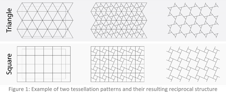
The first step of the generative design for the reciprocal frames is generating a two-dimensional reciprocal frame. This is achieved by applying the center-to-center method on an equilateral polygon tessellation. This research encompasses the optimization of five distinct pattern types: Triangular, Squared, Snub-Square, Honeycomb, and Trihexagon.
From this 2d reciprocal structure, a three-dimensional reciprocal frame structure is generated by looping over the beam elements and increasing the z-coordinate of each of the nodes when the conditions are not met. To perform this looping, additional geometrical elements are added to the reciprocal frame geometry; connection lines (see Figure 2). These lines are used to check if the eccentricity conditions are satisfied: the length of the connection line should be larger than or equal to the required eccentricity and the z-coordinate of the beam node should be ‘eccentricity’ larger than the z-coordinate of the connection beam node.
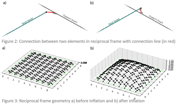
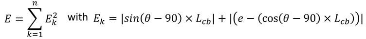
The resulting ‘inflation’ transformation can be seen in figure 3. The inflated geometry however does accurately represent the structural behavior, as the connection lines should ideally be perpendicular to both beams (see figure 2b). To make sure that both these conditions are met a mathematical minimization (L-BFGS-B) is applied that minimizes the model ‘error’ by adjusting the node coordinates. The model error is described as:
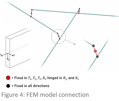
Using the correct geometry that is found after the optimization, the internal forces are calculated using a FEM line model. The connection lines are split to achieve the correct connection behaviour. The individual cross sections of the beam elements are optimized using a custom ‘step-by-step’ optimization that iteratively finds the optimal beam dimensions by using a monotonic sizing optimization.
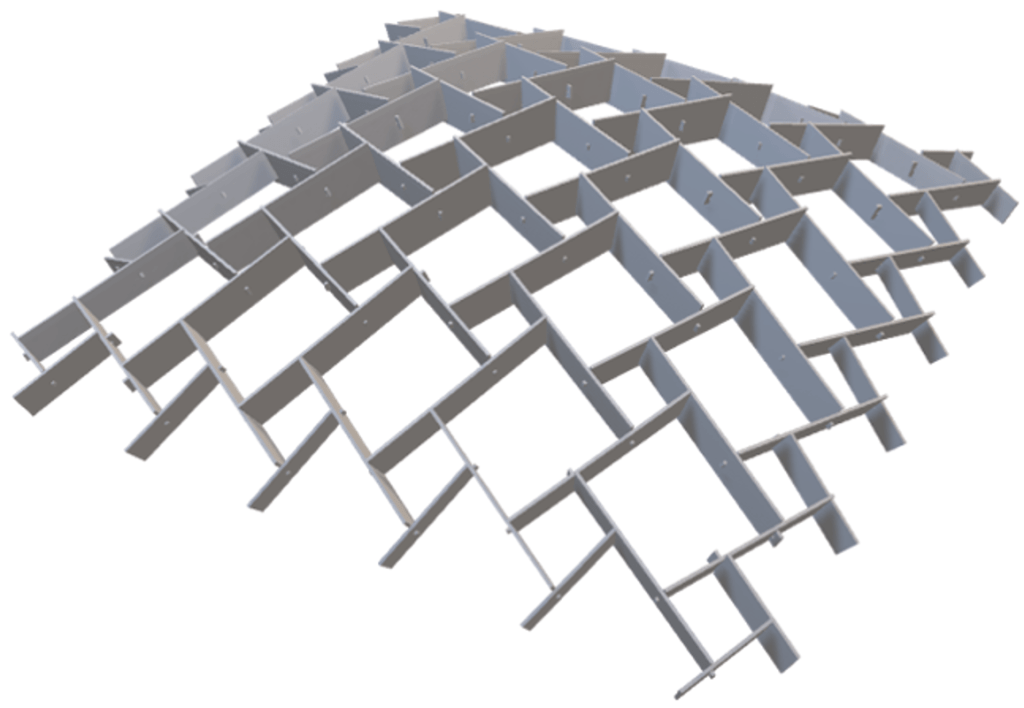
The resulting optimized structure is exported to STL files for digital manufacturing (see Figure 6). Additionally, a cutting pattern is generated that is used to find the minimum plywood sheets required to create the reciprocal structure.
Geometry optimization
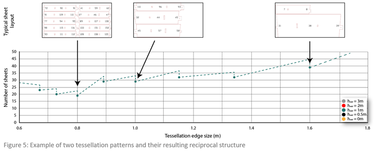
To optimize the reciprocal frames to minimize the number of plywood sheets required (to obtain the beam elements), the parameters that are used in the generative design must be finetuned. Figure 5 shows the influence of the tessellation edge size on the amount of plywood sheets for a square RF. The number of plywood sheets is significantly reduced when two rows of beam elements can be fitted on the plywood sheets. From this, it can be concluded that there is a large potential for optimizing for raw material. In this research, a full optimization of the design parameters has been performed using the Bayesian optimization algorithm. This results in the geometry for each pattern that can be seen in the structural models. The triangle and square pattern are most efficient (using 21 x 2.4×1.2×0.021m sheets). The other patterns are less efficient (the number of sheets required per pattern is displayed on the model).