Student: Rick Damoiseaux
Supervisors : Arjan Habraken, Faas Moonen, Marta Gill Perez, Jelle Versteege
The primary focus of this thesis project is to design a three-dimensional structure using bio-based materials, specifically flax fibers, and to fabricate it using the Coreless Robotic Filament Winding (CRFW) technology. But why is this research performed. The main problem objectives are the reduction of climate emissions and waste produced in combination with the increasing demand for sustainable structures. Some reference projects already use new building methods, such as robotic winding and more sustainable materials, such as Sisal rope or Flax rovings.
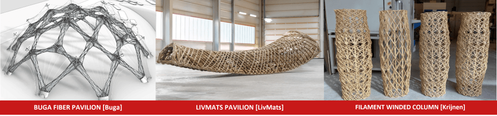
left + middle: ICD/ITKE University of Stuttgart
right: Eindhoven University of Technology
Desing Phase
The first step is the structural element’s design. The goal is to create the form without a core. One solution for this goal is to incorporate a lattice layer with the first sequence of winding lines, this principle is used in the BUGA fiber pavilion.
ICD/ITKE University of Stuttgart
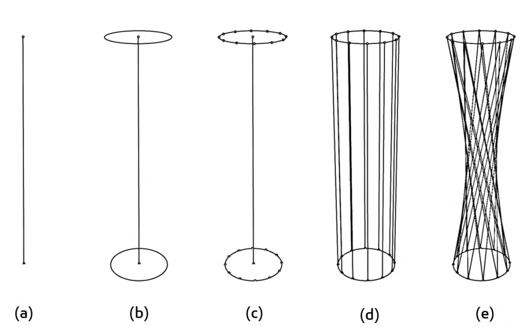
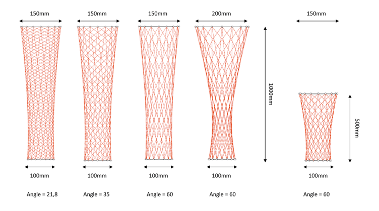
This scaffolding will determine the final element’s shape. As depicted in the image below, the design is based on the number of points around which to wind. By moving the top points relative to the bottom points, a hyperbolic shape emerges. This form is advantageous because it improves the connection between fibers. The fiber-to-fiber connection is important because it can significantly reduce fiber span. In addition, this shape encourages the collection of material in the center of the column. The center of the column is the weakest point of the column, so more material is advantageous to make the column less weak. This follows from the literature by Christie et al. (2021).
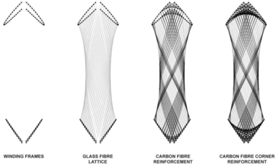
The next step involves winding additional diagonals around this anticlastic shape. Using the Python module in Rhino Grasshopper, it is easy to generate several options for different types of surfaces.
Optimization Phase
With the implementation of the diagonals and a fully working script, the phase of optimization has now begun. As a starting point of the shape optimization, the winded structure was considered loaded in uniaxial compression (with no curvature), an anticlastic structure and combination of two anticlastic shapes that has a sinclastic shape. Considering it as a shell structure to limit the influence of the arrangement of material of the winding lines, the combination of two anticlastic shapes came out as the stiffer structure. However, the shape is of great influence for accumulation of the material at the weaker zones of the structure.
The anticlastic variant namely performs better than the other variants when material properties are considered as tough instead of highly elastic. The anticlastic shape is advantageous for fabricating the design with the robots, therefore the traditional compression-loaded shape actually drops out immediately and is only used for comparison.
The shape study showed that the anticlastic shape would be the most optimal as the final design. It then became clear that it is difficult to perfectly recreate the final shape in reality as represented by the model. This is because the flax fibres will deform when the diagonal layer is applied during the winding process.
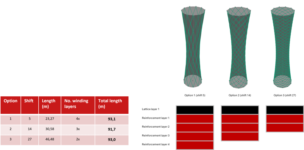
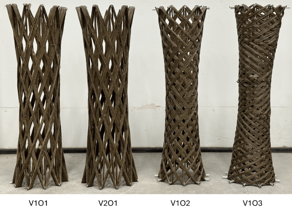
As a result, an approach featuring three different designs, each representing a different configuration of the diagonal angle, is adopted. In order to ensure design consistency across the three variants, attention is paid to determining the required fiber length and therefore maintaining the same mass for three different variants. It is necessary to ensure uniformity in fiber length among the variants, so an examination of multiples within each configuration of the design is conducted. In particular, fiber length depends on three key design input parameters: 1) the radius of the upper and lower end circles, 2) the number of points distributed along these end circles, and 3) the angular orientation of the reinforcement layer relative to the axis of the structure. Of note is the fixed nature of the lattice layer within each design, which maintains a consistent shift of 1 point.
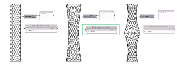
Octopus is used to optimize the final design of the structure. The optimization procedure proceeds generating two different designs in which the radius and number of points remain consistent while the angle of the diagonal lines varies. This process produces two designs characterized by different total fiber lengths. A script is then written to maximize the length of one design and minimize that of the other. Moreover, an additional function is incorporated to ensure that only solutions that satisfy a specified criterion are generated; namely, the lengths of the designs must be within a tolerance range of 0.5 units, by means of a true boolean condition. This condition specifies that the length of one design always closely matches twice the number of meters of the other design, so that there is a consistent relationship between the two designs and thus they are multiples of each other.
Due to the complexity of identifying three feasible options within the existing Octopus script, Microsoft Excel is used to select the third option. All relevant data regarding the lengths of the optimized design were exported to an Excel spreadsheet. Through empirical analysis, an appropriate shift is determined that could be included as the third design option.
Manufacturing Phase
The result is three options with different configurations. In Rhino Grashopper, a path is generated which is then processed using Robot components plugin and Robot studio into a Script that can be used to start producing the elements with the robot. Simulating the robot script can be used to validate the set-up of the robot model.
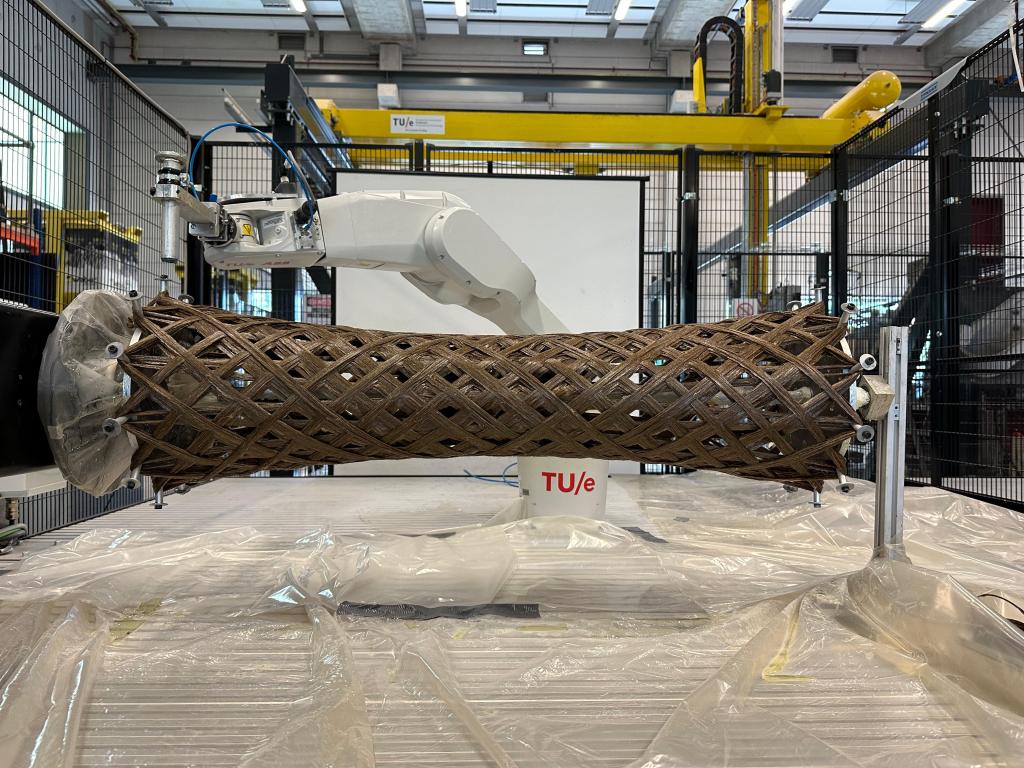
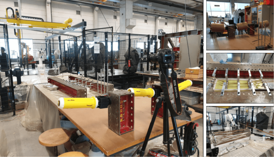
After which, production of the elements can then proceed. Before producing the elements, a set-up needs to be made for the Filament winding process. There was already an existing set-up for filament winding at TU/e, however it was based on impregnating and processing a single piece of sisal rope. To produce the coreless filament wound structures from flax fibers, it was chosen to impregnate three flax fibers simultaneously and then bring them together to form a bundle.As shown in the image below, a new resin bath, a new end-effector and a new end-plate set-up were made.
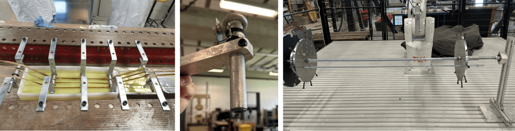
This resulted in the final set-up which is used to produce the composite elements. With all phases of the manufacturing process complete, the winding of the final structure may begin. The first round of winding served to test every aspect of the fabrication process, since no previous testing with flax fibers was done. The total manufacturing process utilized in the first round of winding is shown in the figure below.
following a series of specific steps. First, the flax rovings were removed from the oven and weighed to determine their dry weight. Next, these rovings were taken from the bobbin holders into the resin bath to be impregnated with epoxy resin. After impregnation, the three rovings were assembled into a single bundle. This bundle was guided around the winding pins of the supporting structure by the robot. The video below shows the manufacturing of one of the composite elements.
After the filament winding process, the structures are taken off the robot set-up and transmitted to the climate-controlled room in the SED lab, where they are kept at ambient temperature. This procedure is followed to maintain a minimum temperature of 20 degrees Celsius. The next morning, the structures are moved to a different climate room set at 40 degrees Celsius for an eight-hour post-curing period. This resulted in four manufactured structures after the internal formwork is removed.
Testing and Analysis Phase
Two models were created to analyze the structures which were made. One model was set up to analyze the behavior of the structure during the winding process, called the staging model and created in Oasys GSA. The second model was set up to analyze the how the structure behaves when it will be tested in the test bench in the SED lab, this model is the test model and was created in Karamba3D which is a plugin of Rhino Grasshopper.
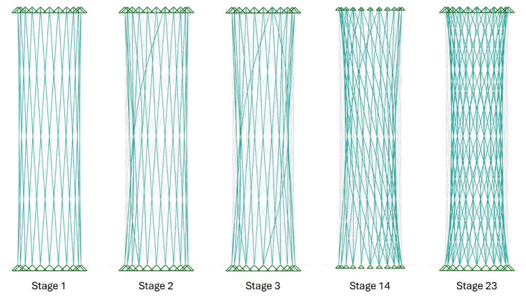
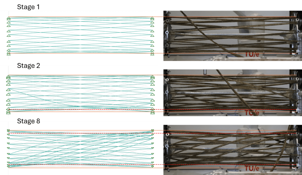
In the figure above the staging model is shown. This model is created to simulate the behavior of the winding lines during the manufacturing of the elements. Since the pre-tension in the winding lines is not known, no real values have been used in this model configuration and this model focuses only on design option 1. The results of the staging analysis are very promising since the model clearly represents reality as can be seen in the figure below. For example, at stage 8, the structure is expected to deform in some assymetry. In reality, this turns out the same way.
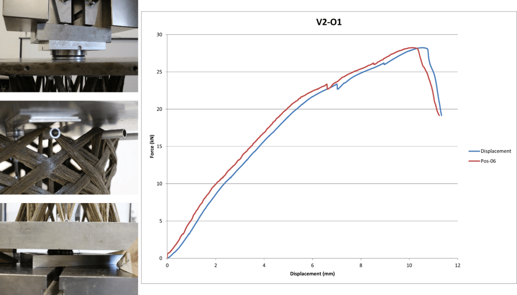
The four fiber composite structures are tested in axial compression using the Instrom compression testing machine in the SED lab at TU/e. The structures were simply supported, allowing them to rotate freely at the structure supports while being fixed to prevent movement. To distribute the load across all bundles and to equalize any unevenness between the bundles aluminum plates were used to fill the open spaces. Thus, each bundle is loaded simultaneously. A spherical hinge is positioned at both the top and bottom, with a steel plate attached to this hinge to cover the end of the structure and distribute the axial pressure point load uniformly across the structure. The test of the structures resulted in a maximum compressive force of 28.5 kN.
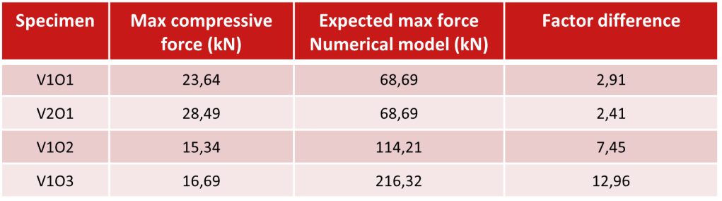
For a comparison between the laboratory test result and the numerical model results, the table below summarizes the axial compression test results, showing the maximum compression force achieved and the maximum force according to the numerical model.
Discussion
The comparison between the test results and the numerical model predictions for the axial compression tests reveals significant differences. The maximum compressive forces observed in the physical tests are considerably
lower than those predicted by the numerical models. Possible reasons for these differences may be:
- Material properties and assumptions;
- Fabrication errors and imperfections;
- Test Setup and Boundary Conditions.
As a dicussion about the complete project, the following notes had to be taken into account for further research:
- The use of bio-based materials like flax fibers marks a significant step forward in sustainable construction, reducing CO2 emissions compared to traditional materials. This study highlights the potential of flax fibers in meeting sustainability goals, but notes the challenge of requiring a resin, which in this case, is only partially bio-based (38%). To fully realize sustainability, a 100% bio-based resin is needed;
- The manufacturing process generates considerable waste, including leftover resin and disposable materials. CRFW technology, while reducing waste and enabling complex designs, faces challenges like ensuring consistent fiber tension and resin impregnation, requiring further iterations to improve quality;
- The current resin’s 50-minute pot life is adequate for small composites but limits the production of larger elements. Robotic limitations further complicate the process, and attempts to adjust the robot’s end-effector were unsuccessful. A potential solution involves connecting smaller elements to create larger structures, with a focus on the strength of these connections.
Conclusion
This research project focused on designing and manufacturing a three-dimensional structure using biobased materials and Coreless Robotic Filament Winding (CRFW) technology. By utilizing flax fibers impregnated with partially bio-based epoxy resin, the study aimed to tackle environmental impact and labor shortages in the construction industry. The research began with a literature review on robotic filament winding, lightweight structures, and axially loaded simply supported structures, revealing that buckling is the primary failure mechanism for slender structures under axial compression. The digital design process, using Rhinoceros, Grasshopper, Karamba3D, and Octopus software, resulted in three optimized anticlastic-shaped designs. These designs were optimized based on the fiber length required for manufacturing, maintaining consistent mass across the variants. A continuous winding path was developed, allowing the structure to be manufactured in one session using RAPID-code in Robot Studio. The robot’s end-effector and resin bath were modified to improve the impregnation of natural flax fibers. The final structure was manufactured with Depestele FR 2400 flax rovings and InfuGreen 810 epoxy resin, following tests with sisal rope. Four structures were produced using the ABB IRB 1200-5/0.9 robot. Numerical modeling and real-time monitoring indicated that local buckling occurred before global buckling, highlighting differences between predictions and actual results. Despite promising structural performance, the study identified the need for further research to enhance accuracy, reduce variability, and scale up the technology for larger applications. Future research should focus on detailed material characterization, improved numerical models, and the development of tools like a robotic end-effector for measuring pretension in roving bundles, which could significantly improve the quality and efficiency of filament-wound structures.
