Student : Thom Bindels
Supervisors : Arjan Habraken, Faas Moonen, Matthew Ferguson
In this research project, robotic fabrication of structural timber elements is explored, focusing primarily on the connections. Two main types of connections are investigated: mechanical and adhesive. To achieve this, both a digital optimization tool and a robotic system will be developed. The digital tool serves the purpose of optimizing various connection types while considering structural constraints. It enables designers to quickly experiment with and evaluate different connections. Furthermore, the digital model enables seamless and quick transformation into robot code, which operates the robotic setup.
The first model focusses on mechanical fasteners such as regular threaded screws. First, the model identifies the contact areas among different timber members where connections are necessary. Second, it calculates and subtracts the edge and end distances from the available gross joint area. Third, within this reduced area, it fits a parallelogram aligned with the load direction. In doing so, it optimizes the area by first ensuring the minimum required perpendicular distance and then maximizes the parallel distance. Last, the tool computes the shear resistance of the connection, including group effects occurring for multiple fasteners.
This model is not confined to a single joint. Its universal applicability allows it to identify any joint and generates a suitable fastener layout for it. As a case study, a truss is implemented that is connected to a GSA model, which gives the member forces. Knowing the members and corresponding forces enables the digital tool to generate the connections for each joint of the complete truss.
Part of the research project is the investigation of a robotic adhesive application process. A peristaltic pump is used to realize this process, where in this stage regular carpenters glue is used. The peristaltic pump has good control over the dosage (ml/min), but due to the relatively high viscosity of adhesives care must be taken. An experimental setup has been developed where for different pump and robot speeds the quality of the glue line is assessed. The choice for a certain pump speed comes from the balance between process speed and glue line consistency. In the next step, samples fabricated using this choice are compared to a traditional process in a single lap (tensile) shear test.
To evaluate the robotic fabrication process, shear tests are performed on a double lap joint. During these tests, a traditional fabrication method is compared to the robotic one. The results of these shear tests give force-displacement behavior, and if these results are equal the robotic process is considered at least equally reliable to traditional methods.
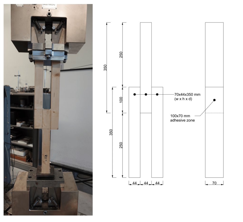
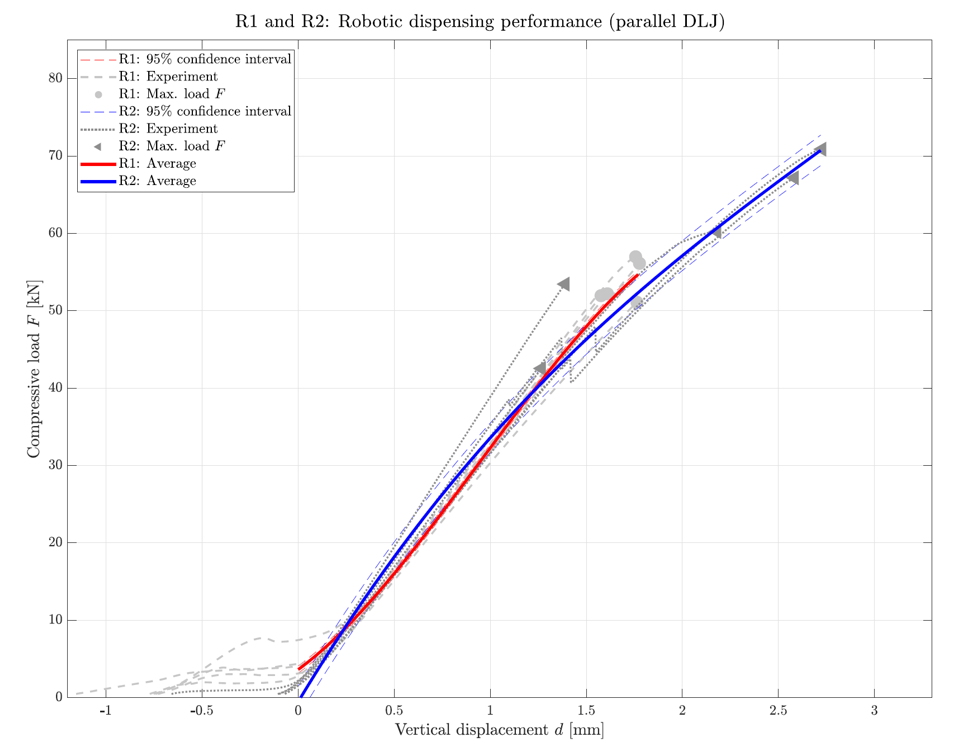
The shear tests are displacement controlled at a rate of 1 mm/min, and achieved a remarkable shear strength of around 55 kN. Moreover, the robotic process and the proposed screw-clamping to introduce the curing pressure both performed similar, or in many cases better, than the traditional fabrication process. Another take-away from these experiments is the extremely high stiffness of the joint. For 55 kN, displacements of only 1.72 mm were recorded. This also is evident from the type of failure occurring, as it was extremely brittle and explosive. These failure modes occurred where the adhesive joint itself failed very suddenly. Other types of failures occurred as well, often related to the timber failing. These types of failures initiated in the center of the middle timber member, which started splitting parallel to the grain. This behavior was caused by the forces developing normal to the adhesive planes.
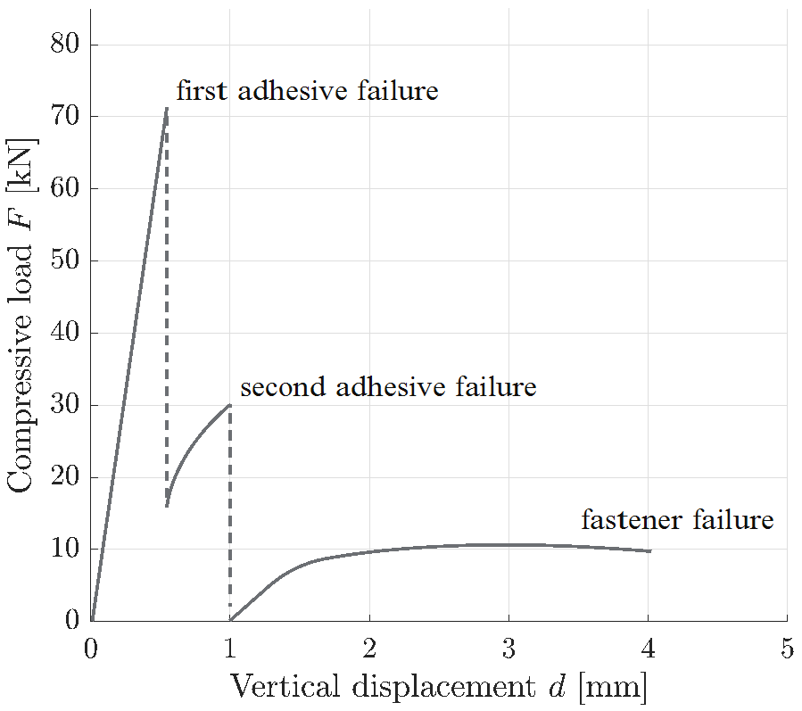
Another type of test that has been performed is the one where the screws were left in the connection. So, this is a connection with two adhesive layers as well as two screws through them. The idea behind this is twofold: The screws need not to be removed reducing the amount of actions the robot must perform, as well as it function as a second load path. During these tests interesting findings were observed, as when the first adhesive layer fails it cannot disassemble as the screws keep the joint together. For increased loading, the resistance in turn starts increasing again until roughly half the total failure load. At this point, the second adhesive layer fails and the joint suddenly becomes one that is only fastened using two screws. For increased loading, the screws start taking over the load, but in this case was very small compared to that of the adhesive layers. This is due to the fact that those two screws were far from designed for a load of 60 kN. However, these effects can already be considered (and designed for) during the initial phases. This offers the possibility that the joint can be designed such that in case of an accidental load the screws provide a ductile second load path, while during normal circumstances the adhesive provides a very stiff joint with little deflections. The conceptual behavior of such a hybrid joint is shown in the figure below.
In the experimental tests absolute shear strengths of the double lap joints have been measured. After this, a numerical study using ABAQUS has been conducted to assess the stresses in the adhesive joint. From literature it is known that adhesive stresses are very localized with large portions of the joint unstressed if not designed properly. Therefore, it is important to understand the adhesive properly so that the bond length can be chosen economically. Moreover, due to these localized stresses, an average shear stress does not mean a lot as the large unstressed portions make this measure not representative.
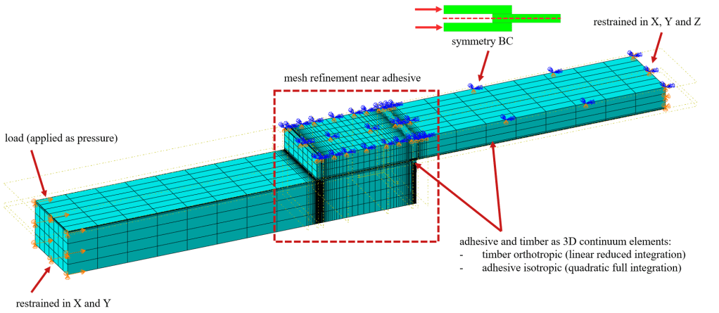
To do this, a FEM model has been constructed. The FEM model consists of the following aspects:
- Both the timber and adhesive are modelled as 3D volume elements. In the adhesive these elements are quadratic HEX bricks, as well as in the transition zone of the timber. The remainder of the timber consists of linear elements to reduce computational times.
- The elasticity of the timber is measured in the lab and used as the compressive E-modulus.
- The load is introduced as a surface pressure at the same end as in the experimental setup.
- Symmetry of the joint is utilized to halve the model and improve computation times.
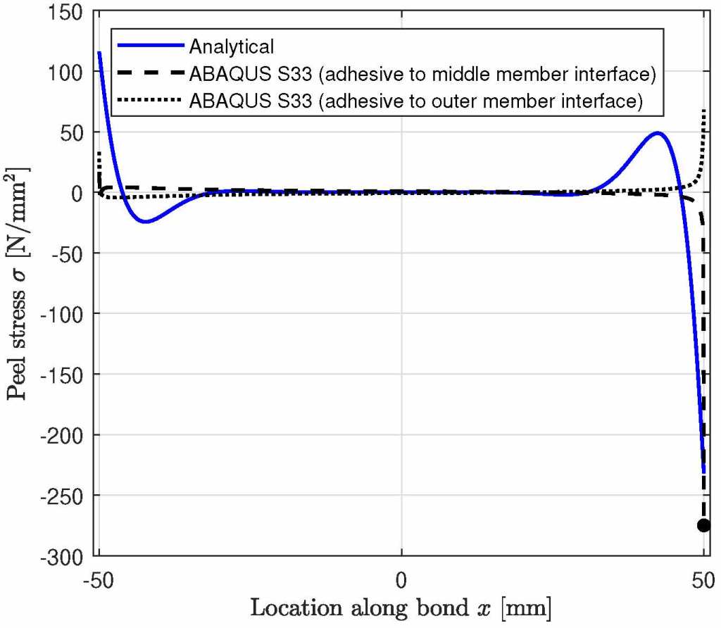
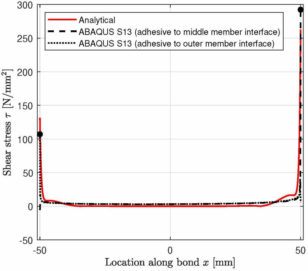
In addition to this model, an analytical model for DLJ joints is compared as well. The results can be seen in the graphs. It can be seen that the distribution of the stresses is relatively similar. It corresponds with literature in the sense that there are very localized stress peaks near the ends of the adhesive, which dictate failure of the joint.
There are some differences between the magnitudes in the FEM and analytical model. This can be due to a variety of reasons, some of which having to do with the assumptions and limitations of the analytical model. Moreover, the combination of a very stiff and thin adhesive layer compared to the relatively pliable and thick timber members can also cause different effects. Moreover, there are certain parameters in the models that have been proven to affect the magnitudes of the results significantly. For example, the adhesive thickness can greatly affect the magnitude of the stresses, and in this case an assumption has been made for this parameter.
From these results it is clear that predicting failure in adhesive joints is relatively complex due to its stress distribution. Moreover, due to the sensitivity of the models to certain parameters it is difficult to make a safe prediction. However, in almost all cases the adhesive has proven to be stronger than the timber shear resistance. It can be a possible avenue to explore whether using the timber properties, and ensuring that the adhesive always exceeds this strength, can be a suitable criterion to determine the joint strength.
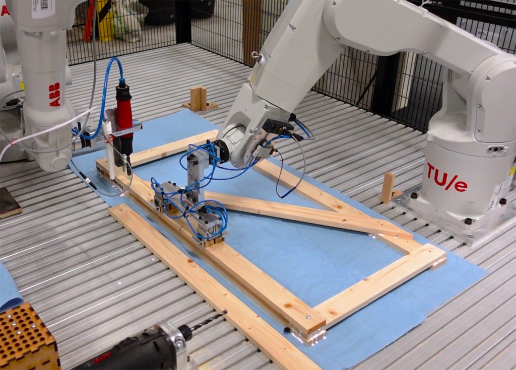
The robotic process integrates various steps in the fabrication of a truss: pick-and-placing, predrilling, gluing, and screwing. All these processes have their own independent subsystems that work together using the MultiMove capabilities of ABB. First, all the subsystems have been developed and their parameters were fine-tuned. Next, the different tasks were combined using wait signals so that robots do not interfere. For the screwdriver, the developed system using the pneumatically activated RODAC screwdriver by Vrenken is utilized.
For the adhesive dispensing system, a 3D-printed nozzle has been designed that can be used together with the screwdriver. This nozzle is connected to the Qdos peristaltic pump, which is a suitable pump type for the viscous adhesives. Moreover, it has good metering capabilities and thereby control over the amount of dispensed material. Next, tests have been conducted to determine the pump rate, dispensing pattern, and robot speed. A key indicator in these tests was that the adhesive lines should be continuous. Therefore, a reliable amount of adhesive is being dispensed.
For the predrilling system, a stationary setup is used where the AMB milling motor is clamped horizontally. The parallel gripper orients the timber piece in front of the milling motor, and then moves with a constant speed of 5 mm/s forward. The drill is operated at an RPM of 3500 rev/min. The forward robot speed has been fine-tuned so that the timber is not burned and the hole is drilled correctly. Ideally, the hole is drilled in between the two grippers of the parallel gripper. However, this is not possible in cases where the hole needs to be at the end of the timber member. In these cases, it is possible to grip the members so that they extend out of the parallel gripper slightly. However, this distance is limited to 100 mm, as further distances will case the timber to be pressed out of the parallel gripper by the drill.
The complete robotic process takes 35 minutes to run, but can be improved on many aspects to increase the efficiency. During the process, the robot first predrills all the required clearance holes in the timber and places them on a temporary stack. After this, the robot applies the adhesive and places the following layer of members. Last, when the final layer is placed, the screws are screwed in. These screws pass through the clearance holes in the upper two layers and only screw in the bottom member. This ensures that the joint is clamped together and the adhesive is properly bonded.
Combining all these tasks proved challenging, as the available space and reach of the robots is relatively limited. Additionally, the timber members can be quite long, and due to the repositioning required for the predrilling of the holes many maneuvers had to be made with relatively large turning radii. The robotic setup can improve most from an increase in available working area. May that either be by using larger robots, or robots that can move on for example linear tracks. This enables the robots to fabricate larger elements that are more representative for structural elements.

