Student : Vincent Staat
Supervisors : Arjan Habraken, Faas Moonen, Matthew Ferguson
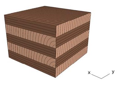
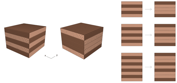
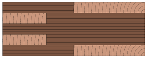
In this master thesis the research goal is to set up an optimization method and tool for optimizing CLT floors. This optimization will be done by varying the direction of planks within the individual layers of CLT so that the strongest direction of the wood is more in line with the geometry, loading conditions and supporting conditions of the floors. The first step was to determine how to rotate the planks. As a starting approach it was decided to rotate the outer two layers of a CLT cross-section. This way, the major direction can be changed while there are always continuous layers running throughout the entire floor. This method only works for CLT with 5 layers or more. An example of the rotation of planks to turn the minor direction of a CLT floor into a major direction can be seen in the figure attached.
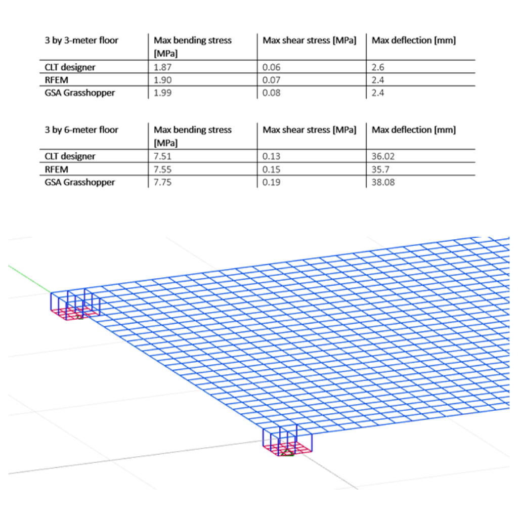
The optimization tool is programmed in Rhino Grasshopper. The shape of the floor is defined using regular grasshopper components. The calculation of the forces and moments in the floor are calculated using the Oasys GSA plugin for Grasshopper. From these forces and moments, the bending, normal and (rolling) shear stresses in the CLT are calculated using established equations. Based on these stresses it is determined what the major direction should be in each 20cm by 20cm part of the floor (the size of these parts can be changed). To verify the calculations the results from the set up script were compared with those of Dlubal RFEM and CLT designer, both commonly used softwares for calculating CLT. The results were deemed accurate enough to base the optimization on. The figures below show the comparison of the results and the way point supports are automatically modelled in the script to prevent unrealistic stress concentrations.
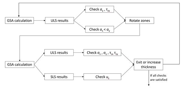
The CLT optimization tool has been expanded to not only optimize for stresses but also for deformations. Given that deformations (and vibrations and stresses perpendicular to the grain at the supports which are features that should be incorporated into the tool in future development) are often governing over stresses for CLT floor it is a necessary aspect to add to the optimization tool. The optimization now works as shown in the diagram below. The major direction of the floors is first determined based on the stresses. These major directions are then applied to the floor and all the stresses and deformations (based on a slenderness value) are checked. If any of the stresses or deformations are beyond the set limits, the thickness of the floor is increased until a solution is found.
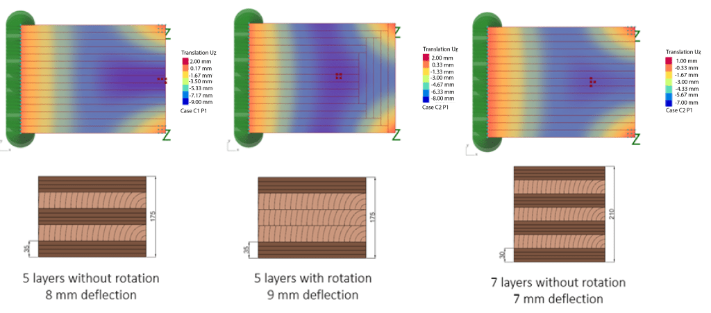
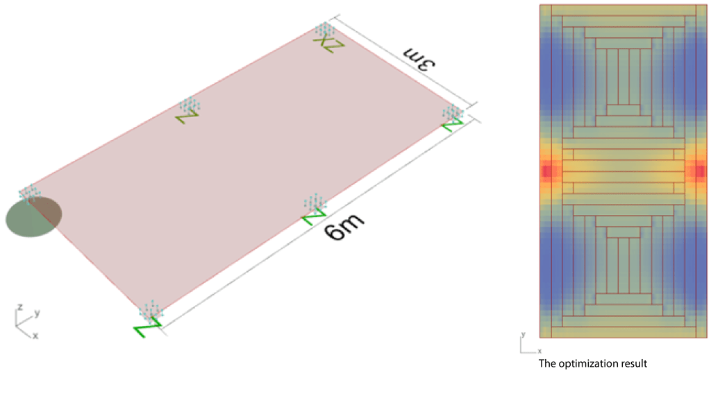
After experimenting with the optimization tool for various case studies interesting results have been found. For some floors the optimization method is not efficient. Think of floor where the major direction of the floor should be in the same direction for every part. For other floors the optimization lead to interesting optimized floors. One of these promising case studies is shown below where a 3m by 4m floor line supported on one side and point supported on the other side was ran through the optimization. The optimization showed that the floor can satisfy the deflection and stress requirements with 5 layers of 35mm thick. This result, the rotation pattern and the location of the largest deflection can be seen in the first figure. To gain insight in these results the same floor was calculated with 5 layers of 35mm thick without any rotation. This floor does not pass the deflection check as the largest deflection is situated along the short edge as indicated in the second figure. Only if seven layers of 30mm thick are used without rotations there is sufficient stiffness to relocate the maximum deflection back to the middle of the floor where it is allowed to be larger (figure 3). The optimization tool found a solution where the maximum deflection is greater compared to a floor without rotation but because of the optimization the behaviors of the floor was adjusted such that the stiffness was increased where necessary leading to satisfying the requirements with 17% less material as compared to a non-optimized floor.
A critical part of the optimized CLT floors is the locations where rotated and non-rotated parts of the floor move. A simple Abaqus simulation was performed to study the possible stress concentrations in these parts. It was expected that they could become problematic and the Abaqus optimization confirmed this. To overcome these stress concentrations various future developments of the optimization method are proposed such as including the possibility of screw reinforcement and by introducing some form of overlap between layers at the areas where a rotated and non-rotated zone meet (see figure below). It is clear that more work needs to be done before the tool can be fully used but it is expected that the currently identified problems can realistically be solved.
This master thesis on setting up with an optimization technique and tool for CLT floors concludes with a proof of concept. This proof of concept shows theoretical material savings of up to 25% as is the case for the floor shown in the figures below. This floor can be made with 5 layers of 30mm if rotation is implemented as opposed to 5 layers of 40mm required to satisfy all included checks if no rotation is implemented. The key words here are “included checks”. More checks and features need to be added to the tool to make it safely usable. Additionally, more FEM and laboratory tests on optimized floors need to be performed to study their behavior and performance. These further steps are beyond the scope of this single master thesis so are proposed as future research steps. The final result of this master thesis is a promising new and innovative optimization method and tool that shines light on the possibilities for more research on optimizing the behavior of CLT.
